
- Home/
- GATE ELECTRICAL/
- GATE EE/
- Article
Sequential Circuits Study Notes for GATE, Electrical (EE) and ECE Exams
By BYJU'S Exam Prep
Updated on: September 25th, 2023

In this article, you will find the detailed study notes on Sequential Circuits which will cover the topics such as Introduction, All types of Flip Flops with implementation, Truth Table, characteristic table and equation, Master-slave Flip Flop, and Flip Flop Conversions. Go through the complete Sequential Circuits notes for GATE, ISRO, ESE, Electrical (EE), and ECE exams.
Table of content
1. Introduction

The sequential circuit is of two types:-
- Synchronous Sequential Circuit: In these Change in the input signals can affect memory elements only upon activation of clock signals pulse.
- Asynchronous Sequential Circuit: In these Changes in input signals can affect memory elements at any instant of time. These are faster than the synchronous circuit.
2. Flip Flops
- It is a 1-bit memory cell that stores the 1-bit logical data (logic 0 or logic 1).
- It is a basic memory element system.
- The most adopted used application of flip flops is in the implementation of a feedback circuit.
- As a memory depends on the feedback concept, flip flops can be used to design it.
- In the synchronous sequential circuit Memory elements are clocked flip flops and generally edge-triggered circuit.
- In the asynchronous sequential circuit, Memory elements are un-clocked flip flops or time delay elements which are generally level triggered.
- Flip flop circuit is also known as a bi-stable multivibrator or latch because it has two stable states i.e. (1 state, 0 states).
For the electronic circuits, there are majorly four types of flip-flops present.
- S-R Flip Flop (Basic Flip Flop)
- Delay Flip Flop (D Flip Flop)
- J-K Flip Flop
- T Flip Flop
Basic SR Flip Flop
- The Set-Reset (also known as S-R) flip flop is designed with the help of two NOR gates or two NAND gates.
SR Latch Implementation Using NAND Gates:

Logic diagram of SR latch using NAND gates

Truth Table of Logic Diagram
SR Latch Using NOR Gates:

Logic diagram of SR latch using NOR gates

Truth Table of Logic Diagram
Clocked SR Flip Flop Implementation using NAND Gates:
It is also known as Gated S-R flip flop. The main problem with S-R flip flops is on using NOR and NAND gate in the invalid state. By using a bistable SR flip-flop this problem can be rectified. This can change outputs when certain invalid states occur, regardless of the condition of either the Set or the Reset inputs in the circuit.
- SR Flip Flop Using NOR Gates:

SR flip flop using NOR gates

Truth Table of SR Flip Flop
Characteristic Table

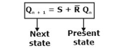
Characteristic equation of SR flip flop
Excitation Table

JK Flip Flop
A JK flip-flop eliminates the indeterminate state of the S-R type Flipflop. Inputs J and K is similar to the inputs S and R to set and clear the flip-flop (In JK flip-flop, the letter J is kind of set and the letter K is for clear). When logic 1 is applied to both J and K inputs simultaneously, the flip-flop switches to its complement state or can say toggle. If Q=1 then it switches to Q=0 and vice versa.
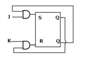
- JK flip flop using SR flip flop:
S = JQ’
R = KQ
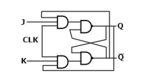
- JK flip flop using NAND latch:
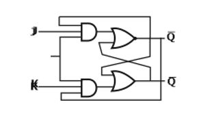
- JK flip flop using NOR latch:
Characteristic Table

Excitation Table

- Characteristic equation for JK flip flop:
![]()
D-Flip Flop
D flip flop also known as a Delay flip flop ,Transparent latch, or data flip flop. The D input goes directly to the S (or J) input and the complement of the D input goes to the R (or K) input.
- The D-flipflop has single data input (D).
- If D = 1, then the flip-flop is switched to the set state (unless it was already set).
- If D = 0, then the flip-flop switches to the clear state.
Truth Table

Characteristic Table

Excitation Table

- Characteristic equation for D-flop flop
Qn + 1 = D
T – Flip Flop
- The T (or toggle ) flip-flop is a single input version of the JK flip-flop where T is connected to both J and K inputs directly.
- When T = 0, the flip flop enters into Hold mode (of Jk flipflop), which means that the output, Q is kept the same as it was before the clock edge.
- When T = 1, the flip flop enters into Toggle mode (of Jk flipflop), which means the output Q is negated after the clock edge, compared to the value before the clock edge.
Truth Table

Characteristic Table

Excitation Table

- The characteristic equation of T-Flip Flop:
Qn + 1 = T ⊕ Qn
- Race Around Condition:
- The race around condition will occur in JK flip flop only when J = K = 1 and tpd (FF) < tpw.
- To avoid race around condition, we must ensure
tpw < tpd (FF) < TCLK
3. Master-Slave (MS) Flip Flop
- A master-slave flip-flop is constructed with two separate flip-flops. One circuit serves as a master while other as a slave. Input clock is applied to master input and Inverted clock applied to slave input.
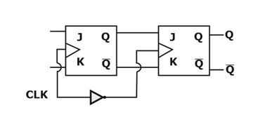
- In Master-Slave, flip-flop output is changed when slave output is changing.
- The master flip-flop is enabled in the positive edge of the clock pulse and the slave flip-flop is disabled by the inverter available in the circuit.
- When the pulse train returns to 0, the master flip-flop is disabled and the slave flip-flop is enabled. The slave flip-flop then goes to the same state as that of master flip-flop.
- Master is level triggered while the Slave is edge-triggered.
- No race-around problem occurs in Master-Slave flip flop.
- It stores one-bit data.
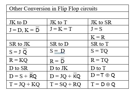
4. Flip Flop Conversions
The flip flop conversions are classified into different types which are:-
- SR-FF to JK-FF Conversion
- JK-FF to SR-FF Conversion
- SR-FF to D-FF Conversion
- D-FF to SR-FF Conversion
- JK-FF to T-FF Conversion
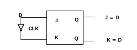
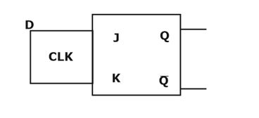
- JK-FF to D-FF Conversion
- D-FF to JK-FF Conversion
Procedure for Flip Flop conversion:
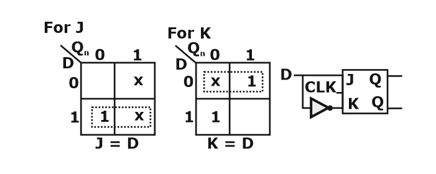
- Conversion Table: Construct the characteristic table of required flip flop (which is unknown), and fill available (which is known) flip flop excitation.
- Solve K map for given (which is known) flip flop as input and required flip flop as output.
- Implement the required flip-flop using the known flip-flop.
Example: Conversion from JK flip flop to D flip flop is shown in below table

Characteristic Table
If you are preparing for GATE and ESE, avail Online Classroom Program to get unlimited access to all the live structured courses and mock tests from the following link :
-
ESE and GATE ECE Online Classroom Program (24+ Live classes and 150+ mock tests)
-
ESE and GATE EE Online Classroom Program (24+ Live classes and 193+ mock tests)
Thank you,
#DreamStriveSucceed


