- Home/
- GATE ELECTRICAL/
- GATE EE/
- Article
What is Compensator in Control System?
By BYJU'S Exam Prep
Updated on: September 25th, 2023

Compensators is an important concepts in the field of Electrical Engineering and Electronics Communication. It is essential tool for ensuring stability, performance, and accuracy in control systems. Compensators are devices that are used to improve the response of a system to input signals by adjusting the frequency response of the system. Controllers are devices that are used to regulate the behavior of a system, based on input signals and feedback.
Compensators Notes PDF(Download)
In this study, we will explore the various types of compensators and controllers used in EE/EC, their design principles, and applications. These study notes will help you understand how to analyze and design compensators and controllers, and how to apply them to real-world control problems.
Table of content
What is Compensator?
Compensators is an important components of control systems that are designed to regulate or maintain a desired behavior of a dynamic system. A compensator is a device that adjusts the response of a system to changes in its environment, while a controller is a device that actively manages the behavior of a system.
Compensators and controllers can be used to ensure that a system is stable and responsive, and can help to improve its performance in a wide range of applications, from industrial control systems to robotics and automation. By carefully selecting and designing appropriate compensators and controllers, engineers can create highly effective control systems that are capable of meeting a wide range of performance requirements.
Types of Compensators and Controllers
Compensators and controllers are essential components of control systems used to regulate and stabilize the output of a system. They are used to improve the performance of a system, increase its stability, and reduce the impact of disturbances. There are several types of compensators and controllers used in control systems, including the following:
- Proportional Controller
- Integral Controller
- Derivative Controller
- Proportional-Integral-Derivative (PID) Controller
What is Compensation Technique?
In Control Engineering, we generally focused on methods used to analyze the performance of a feedback system with a given set of parameters. The results of such analysis frequently show that the performance of the feedback system is unacceptable for a given application because of such deficiencies as low De-sensitivity, slow speed of response, or poor relative stability.
The process of modifying the system to improve performance is called Compensation. The required device added in the control system to obtain the performance as per the desired specification is known as Compensator.
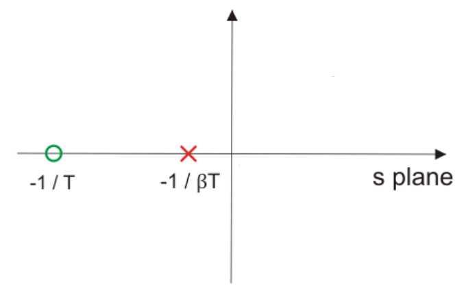
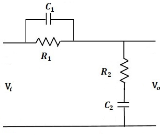
Phase Lead Compensation
A phase lead compensator improves the transient response of the system. As the name implies, this network provides a positive or leading phase shift of the output signal relative to the input signal at all frequencies. Lead-network parameters are usually selected to locate their singularities near the crossover frequency of the system being compensated. The network’s positive phase shift then improves the system’s phase margin.
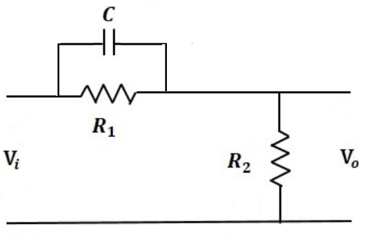
A phase-lead compensator has a transfer function of the form
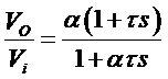
Where,
τ = R1C
α = R2/(R1+R2)
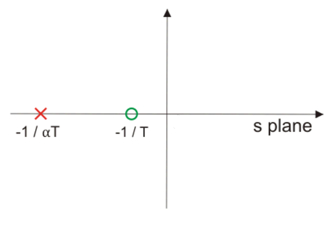
- A Lead Compensator is a high-pass filter.
- Zeros of the transfer function dominate in Phase Lead Compensation Technique.
Phase Lag Compensation
Phase-lag systems are very common. These systems occur when an energy storage unit and an energy dissipator are combined. One example is the RC low pass. The phase-lag compensator has a negative phase angle and so is used to subtract phase from an uncompensated system.
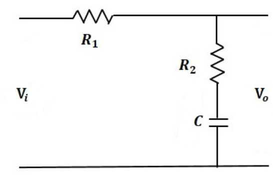
A phase-lag compensator has a transfer function of the form
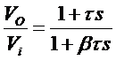
Where,
τ = R2C
β = (R1+R2)/R2
Because the phase-lag compensator adds a negative phase angle to a system, the phase lag is not a useful effect of the compensation and does not provide a direct means of improving the phase margin. The phase-lag compensator does, however, reduce the gain and so can be used to lower the crossover frequency. A consequence of this is that, as the system’s phase margin is usually higher at the lower frequency, the stability can be improved.
In other words, there should not be much change in the location of the dominant poles. The pole of a phase lag compensator lies extremely close to the origin, and it’s zero to the left of the pole and very near to it.
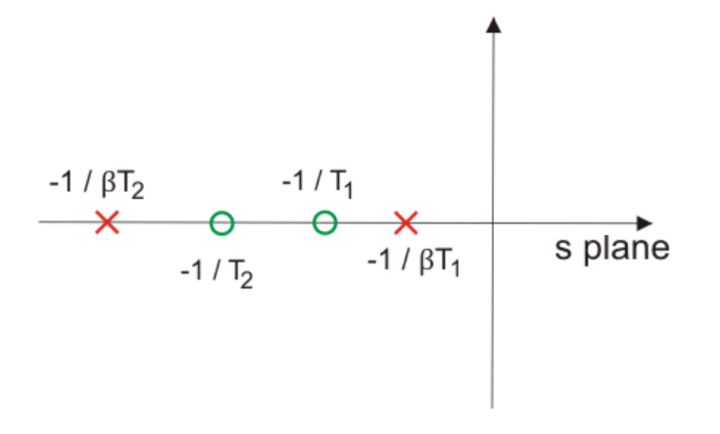
Phase Lag or Lead Compensation
With single lag or lead compensation use, we may not satisfy design specifications. For an unstable uncompensated system, lead compensation provides a faster response but does not provide enough phase margin, whereas lag compensation stabilizes the system but does not provide enough bandwidth. So we need multiple compensators in cascade, i.e. phase lag-lead compensation.
It acts as a band-stop filter.
Controlling Action
The controller (an analog/digital circuit and software) tries to keep the controlled variable, such as temperature, liquid level, motor velocity, and robot joint angle, at a certain value called the set point (SP). A feedback control system does this by looking at the error (E) signal, which is the difference between where the controlled variable (called the process variable (PV)) is and where it should be.
Based on the error signal, the controller decides the magnitude and the direction of the signal to the actuator. The proportional (P), the integral (I), and the derivative (D), are all basic controllers.
Types of controllers: P, I, D, PI, PD, and PID controllers
Proportional Control
With proportional control, the actuator applies a corrective force that is proportional to the amount of error:
Outputp = Kp × E
Outputp = system output due to proportional control.
Kp = proportional constant for the system called gain
E = error, the difference between where the controlled variable should be and where it is. E = SP – PV.

One way to decrease the steady-state error is to increase the system gain (Kp), but high Kp can lead to instability problems.
Increasing Kp independently without limit is not a sound control strategy.
Integral Control
Introducing integral control in a control system can reduce the steady-state error to zero. Integral control applies a restoring force proportional to the sum of all past errors multiplied by time.
OutputI = KI × ∑(E×Δt)
OutputI = controller output due to integral control
KI = integral gain constant (sometimes expressed as 1/TI)
∑(E×Δt) = sum of all past errors (multiplied by time)
For a constant value of error ∑(E×Δt) will increase with time, causing the restoring force to get larger and larger.
Eventually, the restoring force will get large enough to overcome friction and move the controlled variable in a direction to eliminate the error.
Derivative Control
One solution to the overshoot problem is to include derivative control. Derivative control ‘applies the brakes,’ slowing the controlled variable just before it reaches its destination.
OutputD = controller output due to derivative control
KD = derivative gain constant
= error rate of change (slope of error curve)
- Combining P, I, and D controllers
As proportional, integral, and derivative controllers have their individual strengths and weaknesses, they are often combined so that their strengths are maximized, whilst minimizing their weaknesses. Many industrial controllers are a combination of P + I or P + D and are referred to as PI and PD controllers, respectively.
PID Control
A proportional–integral–derivative controller (PID controller) is a generic control loop feedback mechanism (controller) widely used in industrial control systems.
A PID controller attempts to correct the error between a measured process variable and a desired setpoint by calculating and then outputting a corrective action that can adjust the process accordingly.

The foundation of the system is proportional control. Adding integral control provides a means to eliminate steady-state error but increases overshoot. Derivative control increases stability by reducing the tendency to overshoot.
Simply adding together the three required control components generates the response of the PID system.
OutputPID = output from PID controller
KP = proportional control gain
KI = integral control gain
KD = derivative control gain
E = error (deviation from the set point)
∑(E×Δt) = sum of all past errors (area under the error/time curve)
ΔE/Δt = rate of change of error (slope of the error curve)
Equation is:
When designing a PID controller for a given system, follow the steps below to obtain the desired response.
- Obtain an open-loop response and determine what needs to be improved.
- Add a proportional control to improve the rise time.
- Add a derivative control to improve the overshoot.
- Add an integral control to eliminate the steady-state error.
- Adjust each Kp, Ki, and Kd until you obtain the desired overall response.
For more information about this topic, refer to the following video on the Byju Exam Prep’s official youtube channel.
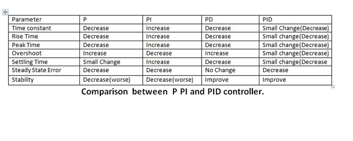
The characteristics of P, I, and D controllers
- A proportional controller (Kp) will have the effect of reducing the rise time and will reduce, but never eliminate, the steady-state error.
- An integral control (Ki) will eliminate the steady-state error, but it may worsen the transient response.
- A derivative control (Kd) will increase the system’s stability, reduce the overshoot, and improve the transient response.