Dear Aspirant,
Today we are covering the study material on Computer Networking, that will help you succeed in the upcoming LIC AAO Exam 2016.
Computer Networks means interconnected set of autonomous system that permit distributed processing to information.
Basic Elements of a Communication System
The following are the basic requirements for working of a communication system.
- A sender (source) which creates the message to be transmitted.
- A medium that carries the message.
- A receiver (sink) which receives the message.
In data communication four basic terms are frequently used.
- Data: A collection of facts in raw forms that become information after processing.
- Signals: Electric or electromagnetic encoding of data.
- Signaling: Propagation of signals across a communication medium.
- Transmission: Communication of data achieved by the processing of signals.
Characteristics of Networking:
- Topology: The geometrical arrangement of the computers or nodes.
- Protocols: How they communicate.
- Medium: Through which medium.
Basic Types of Networks:
Mainly three types of network based on their coverage areas: LAN, MAN, and WAN.
- LAN (Local Area Network): LAN is privately owned network within a single building or campus.A local area network is relatively smaller and privately owned network with the maximum span of 10 km.
- MAN (Metropolitan Area Network): MAN is defined for less than 50 Km and provides regional connectivity within a campus or small geographical area. An example of MAN is cable television network in city. A MAN can be owned by a private company or it may be a service provided by a public company such as local telephone company. Telephone companies provide a popular MAN service called (SMDS) Switched Multi-megabit Data Services.
- WAN (Wide Area Network): A wide Area Network (WAN) is a group Communication Technology ,provides no limit of distance. A wide area network or WAN spans a large geographical area often a country. The Internet is a system of linked networks that are world wide in scope and facilitate data communication services such as remote login, file transfer, electronic mail, World Wide Web and newsgroups etc.
Network Topology
Network topology is the arrangement of the various elements of a computer or biological network. Essentially it is the topological structure of a network, and may be depicted physically or logically.
The common network topologies include the following sections
- Bus Topology: Each node is directly connected to a common cable.

- Star Topology: Each node has a dedicated set of wires connecting it to a central network hub. Since, all traffic passes through' the hub, it becomes a central point for isolating network problems and gathering network statistics.

- Ring Topology: It is logically closed loop. Data packets travel in a single direction around the ring from one network device to the next. Each network device acts as a repeater to keep the signal strong enough as it travels.

- Mesh Topology: Each system is connected to all other systems in the network.
- In bus topology at the first, the message will go through the bus then one user can communicate with other.
- In star topology, first the message will go to the hub then that message will go to other user.
- In ring topology, user can communicate as randomly.
- In mesh topology, any user can directly communicate with other users.

- Tree Topology: In this type of network topology, in which a central root is connected to two or more nodes that are one level lower in hierarchy.


Data Transmission Modes
There are three ways for transmitting data from one point to another:
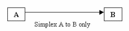
- Simplex: In simplex mode the communication can take place in one direction. The receiver receives the signal from the transmitting device. In this mode the flow of information is Uni.-directional.
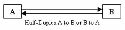
- Half-duplex: In half-duplex mode the communication channel is used in both directions, but only in one direction at a time. Thus a half-duplex line can alternately send and receive data.
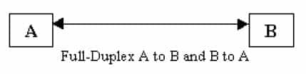
- Full-duplex: In full duplex the communication channel is used in both directions at the same time. Use of full-duplex line improves the efficiency as the line turn-around time required in half-duplex arrangement is eliminated. Example of this mode of transmission is the telephone line.
Digital and Analog Transmission: Data is transmitted from one point to another point by means of electrical signals that may be in digital and analog form.
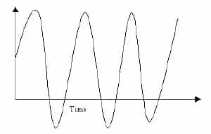
- In analog signal the transmission power varies over a continuous range with respect to sound, light and radio waves. Analog signal is measured in Volts and its frequency in Hertz (Hz).
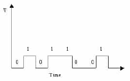
- A digital signal may assume only discrete set of values within a given range.
- When digital data are to be sent over an analog form the digital signal must be converted to analog form. So the technique by which a digital signal is converted to analog form is known as modulation and the reverse process, that is the conversion of analog signal to its digital form, is known as demodulation. The device, which converts digital signal into analog, and the reverse, is known as modem.
Hardware/Networking Devices
Networking hardware may also be known as network equipment computer networking devices.
- Network Interface Card (NIC): NIC provides a physical connection between the networking cable and the computer's internal bus. NICs come in three basic varieties 8 bit, 16 bit and 32 bit. The larger number of bits that can be transferred to NIC, the faster the NIC can transfer data to network cable.
- Repeater: Repeaters are used to connect together two Ethernet segments of any media type. In larger designs, signal quality begins to deteriorate as segments exceed their maximum length. We also know that signal transmission is always attached with energy loss. So, a periodic refreshing of the signals is required.
- Hubs: Hubs are actually multi part repeaters. A hub takes any incoming signal and repeats it out all ports.
- Bridges: When the size of the LAN is difficult to manage, it is necessary to breakup the network. The function of the bridge is to connect separate networks together. Bridges do not forward bad or misaligned packets.
- Switch: Switches are an expansion of the concept of bridging. Cut through switches examine the packet destination address, only before forwarding it onto its destination segment, while a store and forward switch accepts and analyze the entire packet before forwarding it to its destination. It takes more time to examine the entire packet, but it allows catching certain packet errors and keeping them from propagating through the network.
- Routers: Router forwards packets from one LAN (or WAN) network to another. It is also used at the edges of the networks to connect to the Internet.
- Gateway: Gateway acts like an entrance between two different networks. Gateway in organisations is the computer that routes the traffic from a work station to the outside network that is serving web pages. ISP (Internet Service Provider) is the gateway for Internet service at homes.
OSI Model
The Open System Interconnection (OSI) model is a reference tool for understanding data communication between any two networked systems. It divides the communication processes into 7 layers. Each layer performs specific functions to support the layers above it and uses services of the layers below it.

- Physical Layer: The physical layer coordinates the functions required to transmit a bit stream over a physical medium. It deals with the mechanical and electrical specifications of interface and transmission medium. It also defines the procedures and functions that physical devices and interfaces have to perform for transmission to occur.
- Data Link Layer: The data link layer transforms the physical layer, a raw transmission facility, to a reliable link and is responsible for Node-to-Node delivery. It makes the physical layer appear error free to the upper layer (i.e, network layer).
- Network Layer: Network layer is responsible for source to destination delivery of a packet possibly across multiple networks (links). If the two systems are connected to the same link, there is usually no need for a network layer. However, if the two systems are attached to different networks (links) with connecting devices between networks, there is often a need of the network layer to accomplish source to destination delivery.
- Transport Layer: The transport layer is responsible for- source to destination (end-to-end) delivery of the entire message. Network layer does not recognise any relationship between the packets delivered. Network layer treats each packet independently, as though each packet belonged to a separate message, whether or not it does. The transport layer ensures that the whole message arrives intact and in order.
- Session Layer: The session layer is the network dia log controller. It establishes, maintains and synchronises the interaction between communicating systems. It also plays important role in keeping applications data separate.
- Presentation Layer: This layer is responsible for how an application formats data to be sent out onto the network. This layer basically allows an application to read (or understand) the message.
- Application Layer: This layer enables the user, whether human or software, to access the network. It provides user interfaces and support for services such as electronic mail, remote file access and transfer shared database management and other types of distributed information services.
Thanks,
Gradeup.!!


Comments
write a comment