
- Home/
- GATE ELECTRONICS/
- GATE EC/
- Article
Resonance in RLC Circuit
By BYJU'S Exam Prep
Updated on: September 25th, 2023

Resonance in RLC Circuit has a lot of applications. In the electrical circuits, the resonance happens because of the energy storing elements called inductor and capacitor. We will use the concept of resonance in this circuit in the communication system, especially in the receivers, whenever we want to tune the received signal to a particular frequency.
This article gives an overview of resonance in RLC circuits and how to calculate the resonant frequency. First will discuss what resonance is in the series and parallel circuit and then the condition to get resonance in the given network/ circuit. After that, the upcoming sections will discuss the power factor at resonance in the RLC circuit.
Table of content
What is Resonance in RLC Circuit?
We know that Resistor (R), Inductor (L), and Capacitor (C) are the passive elements. We can connect these passive elements in several ways. For the time being, let us consider the basic connections. These are series connections and parallel connections.
If we connect an AC source with variable frequency to the RLC network/ circuit combination, then at one frequency, the energy stored in both inductor and capacitor will be equal, or the net energy stored in the circuit will be zero. This frequency is known as resonant frequency, and we can say that the circuit is at resonance. In the RLC circuit the current at resonance is I = VR.
Types of Resonance in RLC Circuit
Since we have two basic connections, we will have two types of Resonance. Now, let’s discuss the following two types of resonances.
- Series Resonance
- Parallel Resonance
Resonance in Series RLC Circuit
In the series RLC circuit at resonance, we will connect the AC voltage source, Resistor (R), Inductor (L), and Capacitor (C), all in series. This circuit diagram is shown in the figure below.
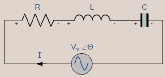
The current is the same in series, but the supply voltage (AC) gets divided among the passive elements.
- Since R, L, and C are connected in series, the equivalent impedance will be Z=R+j(ωL-1/ωC).
- The impedance, Z, will be real, equal to R when the imaginary part of impedance becomes zero at ω=0.
- At ω=ω0, the inductor and capacitor reactance is the same.
ω0L=1/ω0C
=>ω02=1/LC
=>ω0=1/√LC
=>f0=1/2π√LC
- f0 is the series resonant frequency, equal to 1/2π√LC.
- At ω=ω0, V=IZ=IR. That is, voltage and current are in phase at a resonant frequency. i.e., ∅=0.
- At the series resonant frequency, the power factor cos ∅ will equal 1. Hence, it is called a unity power factor.
Resonance in Parallel RLC Circuit
In a parallel RLC circuit, we will connect the AC source, Resistor (R), Inductor (L), and Capacitor (C) all in parallel. This circuit diagram is shown in the figure below.
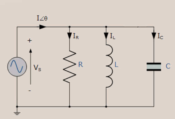
Voltage is the same, but the supply current (AC) gets divided among the passive elements.
- Since R, L and C are connected in parallel, and the equivalent admittance will be Y=1/R+j(ωC-1/ωL).
- The admittance, Y will be real, and it is equal to 1R when the imaginary part of admittance becomes zero at ω=ω0.
- At ω=ω0, the inductor and capacitor susceptance are the same.
ω0C=1/ω0L
=>ω02=1/LC
=>ω0=1/√LC
=>f0=1/2π√LC
- f0 is the parallel resonant frequency, equal to 1/2π√LC.
- At ω=ω0, I=VY=V/R. That is, current and voltage are in phase at a resonant frequency. i.e., ∅=0.
- The power factor at resonance in RLC parallel circuit is cos ∅ , which will equal 1. Hence, it is called a unity power factor.
Therefore, the power factor at resonance in the RLC circuit is equal to 1 for both series and parallel circuits. This article discussed resonance in RLC circuits for both series and parallel connections.


