Introduction of Losses Through Pipes & Compounding
When fluid flows through pipes, there are losses of energy due to viscous or friction and change in pipe diameter or bends in pipes.
Connections of pipes in series and parallel are termed as compounding of pipes.
Energy losses in pipes are divided into two types based on the amount of losses:
- Major Loss.
- Minor Loss.
Major Loss
It is calculated by Darcy Weisbach formula
Loss of head due to friction:

where:
L = Length of pipe
V = Mean velocity of flow
d = Diameter of pipe
f = friction factor
f'=coefficient of friction
f= 4f'
Chezy’s Formula
In fluid dynamics, Chezy’s formula describes the mean flow velocity of steady, turbulent open channel flow.

Average velocity V is given by: ![]()
Where: ![]()
i = Head loss per unit length of pipe (hydraulic slope tanθ)

Minor Loss
The another type of head loss is minor loss which are induced due to following reasons
Loss due to Sudden Enlargement:
Head loss:
Loss due to Sudden Contraction:
Head loss: 
Remember v1 is velocity at point lies in the contracted section.
Loss of Head at Entrance to Pipe:
Head loss:

Loss at Exit from Pipe
Head loss: 
Combination of Pipes
Pipes may be connected in parallel, series or in both. Let see their combinations.
Pipe in Series: In series combination of pipes, the discharge through each pipe will be same.

In series pipes:
(i). Discharge, Q = A1v1 = A2v2 = A3v3
(ii). The total head loss is the sum of the head losses in each individual pipe.
Pipes in Parallel: In parallel combination discharge in main pipe is equal to sum of discharge in each of parallel pipes.

For Parallel pipes:
(i). Total discharge: Q = Q1 + Q2
(ii). Loss of head in each parallel pipe is same.
i.e. Loss of head in branch pipe 1 = Loss of head in branch pipe 2
Hydraulic Gradient Line (HGL) and Total Energy Line (TEL)

HGL → It connects piezometric head at various points.
TEL → It connects total energy head at various points.
Note:
- HGL is always parallel to TEL but lower than TEL by velocity head.
- For stationary bodies such as lakes or reservoirs, the HGL and EGL coincide with the free surface of the liquid.
- A steep jump or droop occurs in HGL and TEL whenever mechanical energy is added to the fluid (by a pump)or mechanical energy is removed from the fluid (by a turbine) respectively.


Water Hammer:
When a liquid is flowing through a long pipe fitted with a valve at the end of the pipe and when the valve is closed suddenly a pressure wave of high intensity is generated behind the valve. This pressure wave of high intensity is having the effect of hammering action on the pipe wall. The phenomenon is known as water hammer.
Introduction of Boundary layer theory
The boundary layer phenomenon occurs when a fluid flows over a flat plate causing laminar or turbulent flow. This topic defines various parameters such as Energy thickness, Momentum thickness, Boundary layer thickness etc.
- Ludwig Prandtl developed boundary layer theory in the year 1904.
- When a real fluid flows over a solid body, fluid velocity at the boundary will be zero. If the boundary is stationary.
- As we move away from the boundary in the perpendicular direction, velocity increases to the free stream velocity. It means velocity gradient will exist.
Note: velocity gradient ![]() does not exist outside the boundary layer as velocity is constant and equal to free stream velocity outside the boundary layer.
does not exist outside the boundary layer as velocity is constant and equal to free stream velocity outside the boundary layer.
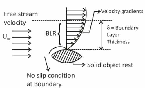
Boundary-Layer Thickness (δ)
It is the distance from the boundary of the solid body measured in the y-direction to the point where the velocity of the fluid is approximately equal to 0.999 times the free stream velocity (U) of the fluid.
Boundary conditions in boundary layer:
(i) At y = 0, u = 0
(ii) y = δ, u = u∞
(iii) y = δ, ![]() =0
=0
(iv) x = 0, δ = 0
Here, x is the distance in the horizontal direction from the leading edge.

Fig.: Boundary layer on a flat plate
Reynolds number (Re) ![]()
For laminar boundary layer (Re)x < 5 × 10⁵ (For flat plate)
For turbulent boundary layer (Re)x > 5 × 10⁵ (For flat plate)
Displacement Thickness (δ*):
It is the distance measured perpendicular from the solid body, by which the boundary should be displaced to compensate for the reduction in flow rate on account of boundary layer formation.


Momentum Thickness (θ):
It is the distance measured perpendicular from the solid body, by which the boundary should be displaced to compensate for the reduction in the momentum of the flowing fluid on account of boundary layer formation.

Energy Thickness (δe):
It is the distance measured perpendicular from the solid body, by which the boundary should be displaced to compensate for the reduction in kinetic energy of the flowing fluid on account of boundary layer formation.

Shape Factor(H):
- The ratio of displacement thickness to momentum thickness is known as the shape factor.
- Hence: H=δ*/θ
- This ratio depends simply on the shape of the velocity profile.
Von Karman Momentum Integral Equation
![]()
where, θ = momentum thickness; ρ = Density of fluid and U = Free stream velocity.

This above equation is applied to:
1. Laminar boundary layers,
2. Transition boundary layers, and
3. Turbulent boundary layer flows.
Local Coefficient of Drag (CD*):
It is defined as the ratio of the shear stress τ0 to the quantity ![]()
It is denoted by 
Average Coefficient of Drag (CD):
It is defined as the ratio of the total drag force to the quantity ![]()
It is denoted by
Where, A = Area of surface, U = Free stream velocity, ρ = Mass density of the fluid.
Total drag on a flat plate due to laminar and turbulent boundary layer:

Total drag= Laminar drag upto transition boundary + turbulent drag for the whole plate - turbulent drag upto transition boundary
Drag force=FD = ½ ρ × v2 × CD ×A
Blassius Experiment Results:

where x = Distance from the leading edge
Rex = Reynold number for length x.
ReL = Reynold number at the end of the plane
For laminar flow, the thickness of the Boundary layer, δ ∝ √x
Shear stress at the solid surface, ![]()
Velocity profile for turbulent boundary layer on Flat surface:

where n =1/7 for Re < 107 but more than 5 × 10⁵
Boundary-Layer Separation
The effect of pressure gradient on boundary layer separation can be explained by considering the flow over a curved surface ABCSD, as shown in Fig.

Along the region CSD of the curved surface, the area of flow increases, and hence the velocity of flow along the direction of fluid decreases. Thus, the pressure increases in the flow direction due to a decrease in velocity. Pressure gradient:
The velocity of the layer adjacent to the solid surface along the length of the solid surface decreases. Thus, the combined effect of positive pressure gradient and surface resistance reduce the momentum.
Location of Separation Point:
The point of separation (S) is obtained from the condition:

For a given velocity profile:
If  the flow is separated
If  the flow is on the verge of separation
If  the flow will not separate
Methods of Preventing Separation of Boundary Layer:
- Supplying additional energy from a blower.
- Providing a bypass in the slotted
- Rotating boundary in the direction of flow.
- Providing small divergence in a diffuser.
- Providing guide blades in a bend.
Introduction of Drag & Lift
A Stationary fluid exerts a force on a moving body in it. The force is also exerted when the body and fluid move at different velocities, i.e., relative motion between them.

Drag (FD):
Drag is the total aerodynamic force (FR) component, which is parallel and in opposition to the body’s motion.
Lift (FL):
The component of the total force (FR) in the direction perpendicular to the direction of motion is known as ‘lift’. Lift force is considered when the axis of the body is inclined to the direction of fluid flow. If the axis of the body is parallel to the direction of fluid flow, the lift force is zero.
Note.:
The drag and lift will be zero for fluid flow over an ideal and symmetrical body like a sphere or cylinder.
Expression for the Drag and Lift:
Consider an arbitrary shape solid body placed in a real fluid flowing with a uniform velocity U in a horizontal direction as shown in Fig. Consider a small elemental area dA on the body’s surface.

The forces acting on the surface area dA are:
- Pressure force equal to P × dA acting perpendicular to the surface and
- A shear force equal to τ0 × dA acts along the surface's tangential direction.
Let θ = angle made by pressure force with the horizontal direction.
Drag force (FD):
dFD = (Fpressure + Fshear) in the direction of fluid motion
dFD = pdA cos θ + τodA cos (90° – θ) = pdA cos θ + τ0dA sin θ
∴ Total drag (FD):
![]()
Where:

The drag and lift for a body moving in a fluid of density ρ, at a uniform velocity (u)
Are calculated mathematically, as:

and
Where:
CD = Co-efficient of drag
CL = Co-efficient of lift,
A = projected area of the body perpendicular to the direction of flow = Largest
projected area
of the immersed body.
The resultant force is:

The relative contribution of the friction drag and pressure drag in the total drag depends on:
(i). the shape of the immersed body.
(ii). the immersed body position in the fluid, and
(iii). Fluid characteristics.

You can avail of BYJU’S Exam Prep Online classroom program for all AE & JE Exams:
BYJU’S Exam Prep Online Classroom Program for AE & JE Exams (12+ Structured LIVE Courses)
You can avail of BYJU’S Exam Prep Test series specially designed for all AE & JE Exams:
BYJU’S Exam Prep Test Series AE & JE Get Unlimited Access to all (160+ Mock Tests)
Thanks
Team BYJU’S Exam Prep
Download BYJU’S Exam Prep APP, for the best Exam Preparation, Free Mock tests, Live Classes.


Comments
write a comment