Chain Surveying & Levelling
Chain Surveying
- It is the simplest and oldest form of land surveying of an area using linear measurements only.
- It can be defined as the process of taking direct measurement, although not necessarily with a chain.
Types of equipment used in Chain Surveying
These equipment's can be divided into three, namely
- Those used for linear measurement. (Chain, steel band, linear tape)
- Those used for slope angle measurement and for measuring right angle (Eg. Abney level, clinometer, cross-staff, optical squares)
- Other items (Ranging rods or poles, arrows, pegs etc.)
1. Chain: This is an instrument used for measuring distance. There are four types of chains.
(i) Metric chain: In metric system the chains of 20m and 30m are commonly used. The chain is made with galvanized steel wire of 4mm diameter. Each meter is divided into 5 links of 20cm length. It is provided with brass handles on either ends. The tallies are fixed at every 5m length and small brass rings are provided at every meter length.
(ii) Engineer’s chain: The Engineer’s chain is 100ft length and made of 100 links.
(iii) Gunter chain: It is 66 feet long and has 100 links. It is useful for measuring the distance in miles and areas in acres.
10 square Gunter chain = 1 acre = 4840 sq. yards.
(iv) Revenue chain: This chain is of 33ft length and is divided into 16 links.
2. Tape: The tapes are divided according to the materials used as following (i) Metallic tapes (ii) Steel tapes (iii) Invar tapes
(i) Metallic tapes: This tape is made with waterproof linen with brass, copper wires to avoid stretching. The tapes available in lengths 2, 5, 10, 20 and 30m.
(ii) Steel tapes: This is most accurate tape for taking measurements. If carelessly handled it gets broken.
(iii) Invar tapes: If the measurements are to be made with the highest precision this tape is used. These are 6mm wide and available in lengths of 30, 50 and 100m.
3. Ranging rods: These are wooden or metal poles 2m or 3m long and having a diameter of 30mm. They are provided with iron shoes at the lower ends to facilitate easy driving in the ground. They are painted in bands alternatively in black and white or red and white. Ranging rods used for ranging a line.
4. Offset rods: This is mainly used to measure offsets of shorter lengths. It is usually 2m long.
5. Cross staff: Cross staff is an instrument used for setting perpendicular offsets. These are three types.
(i) Open cross staff: It consists of 4 metal arms at right angles to each other having eye vane at two adjacent ends and object vane at the other ends.
(ii) Adjustable cross staff: With this cross staff the object can be set at any angle.
(iii) French cross staff: This cross-staff is an octagonal brass tube with slits on its eight faces. With this cross staff we can set the object at an angle of 450 also.
6. Optical Square: This is an instrument used for setting out right angles to the chain lines and to find out the foot of the perpendicular on the chain line from an object. It works on the principle of reflection.
7. Arrows: These are used for marking the ends of a chain during the process of chaining. These are steel pins 400mm long and are pointed at one end.
8. Plumb bob: It is used to define the vertical line while measuring distance along slopes.
General Procedure in making a Chain Survey
1. Reconnaissance: Walk over the area to be surveyed and note the general layout, the position of features and the shape of the area.
2. Choice of Stations: Decide upon the framework to be used and drive in the station pegs to mark the stations selected.
3. Station Marking: Station marks, where possible should be tied - into a permanent object so that they may be easily replaced if moved or easily found during the survey. In soft ground, wooden pegs may be used while rails may be used on roads or hard surfaces.
4. Witnessing: This consists of making a sketch of the immediate area around the station showing existing permanent features, the position of the stations and its description and designation. Measurements are then made from at least three surrounding features to the station point and recorded on the sketch. The aim of witnessing is to relocate a station again at much later date even by others after a long interval.
5. Offsetting:- Offsets are usually taken perpendicular to chain lines in order to dodge obstacles on the chain line.
6. Sketching the layout on the last page of the chain book, together with the date and the name of the surveyor, the longest line of the survey is usually taken as the baseline and is measured first.
Linear Measurements
Tape Corrections
(a) Correction due to standardization or (correction due to absolute length)

where, Ca = Correction for absolute length
L = Measured length of the line
l = Designated length of the tape
C = Correction per tape length
(b) Correction due to temperature
CT = Lα(Tm – T0)
where, Tm = Temp. at the time of measurement
T0 = Temp. at the time of standardization of the tape
α = Coefficient of thermal expansion
L = Measured length
(c) Correction for pull or tension


where, Cp = correction for pull
Pm = pull applied at the time of measurement
P0 = Pull applied at the time of standardization
L = Measured length
A = Cross-sectional area
E = Young’s modulus of tape
(d) Sag Correction


where, Pm = Pull applied, W = Total weight of tap = wl
w = Weight per meter length, l = length of tape
- Case: Normal Tension
At a particular value of pull (where Pm > P0) pull correction and sag correction neutralize each other. This value is called normal tension.
![]()
(e) Correction due to slope


where,
h = difference in elevation between the ends
L = Inclined length measured
l = Horizontal length
Cs = Correction due to sag
(f) Correction due to the wrong alignment


where, L = length measured along wrong alignment
l = Correct length
h = Error in alignment
Limiting Length of Offset
(a) Effect of error in laying out direction only
![]()
where, l = Limiting length of offset
S = Scale (1 cm = S meter)

(b) Combined error in length and direction


where,
X = error in length measurement.
S = Scale (1 cm = S meter)
Levelling
Definitions
(i) Reduced level: The elevation of a point with respect to either Mean Sea Level (MSL) or with respect to a fixed point of known height is called reduced level.
(ii) Benchmark: Benchmark is the relatively permanent point of reference whose elevation with respect to some assumed datum is known. It is used either as a starting point for leveling or as a point upon which to close as a check.
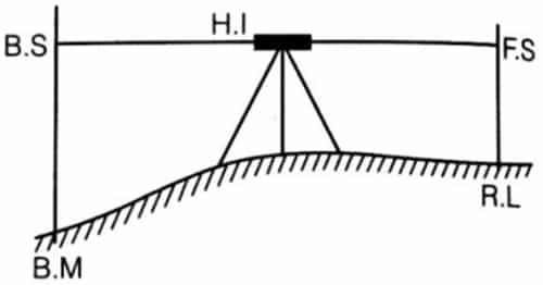
(iii) Back sight: After setting up the instrument Ist reading taken is called back sight. It is also known as plus sight.
(iv) Foresight: Last reading taken from an instrument station is called fore sight. It is also known as minus sight.
(v) Intermediate sight: All readings other than back sight and fore sight are intermediate sight.
(vi) Height of instrument: It is the Reduced Level (RL) of line of sight of the instrument set up at different stations.
H.I = R.L + B.S
R.L = H.I – F.S
Arithmetic Check
(i) For rise and fall method
∑B.S - ∑F.S = ∑Rise - ∑Fall = Last R.L – First R.L
(ii) Height of instrument method
∑ B.S - ∑ F.S = Last R.L – First R.L
Reciprocal Levelling
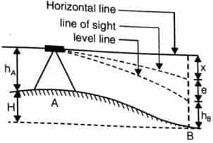
Here, X = error due to inclined line of sight, and
e = error due to curvature and refraction
When instrument is set up at A
Reading on staff at A = hA
Reading on staff at B = hB
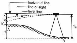
When instrument is set up at B
Reading on staff at A = h’A
Reading on staff at B = h’B
hA – hB = h’A – h’B If instrument is correct.
![]()
Here ‘H’ is the true difference of R.L between A and B.
True Readings

Curvature Correction (CC)

Here, d = horizontal distance between A and B
R = radius of earth
If R = 6370 km
Than CC = -0.07849d2
here ‘CC’ is in meter and ‘d’ is in kilometer

Refraction Correction (CR)

Here d is in kilometer.
Combined Correction Due to Curvature and Refraction (C)

C = -0.06728d2 meter Here d is in kilometer.
Distance of Visible Horizon
d = 3.8553√ckm
Here ‘C’ being in meters. (taking both curvature and refraction into accounts)

Sensitiveness of Bubble Tube
Sensitiveness of the bubble tube is defined as the angular value of one division of the bubble tube.
α' = sensitivity of the bubble tube
= angular value of one division


Here, S = difference between two staff readings.
n = no. of divisions of bubble
![]()
where, l = length of one division
R = radius of curvature of bubble tube.
Contouring
Contours: Contour is an imaginary line joining points of equal elevation on earth surface.
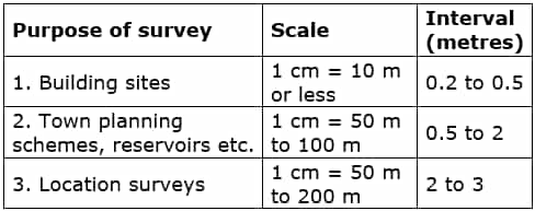
Contour interval: Vertical distance between two contour is called contour internal.
Some suitable value of contour intervals
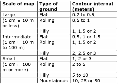
Contour internal for various purposes are suggested as:


Comments
write a comment