- BALANCING OF ROTATING MASSES
In any rotating system, having one or more rotating masses, if the centre of mass of the system does not lie on the axis of rotation the system is unbalanced.
When an unbalanced mass rotating about an axis it experiences a centrifugal force in a radially outward direction. This force is called as disturbing force of the system.
The magnitude of disturbing force is Fc = mrω2
where, Fc = centrifugal force or disturbing force, N
m = mass of the rotating body, kg.
r = distance of centre of mass (C.G) from the axis of rotation, m
ω = angular speed of rotation, rad/s.
- BALANCING OF SINGLE MASS ROTATING IN SINGLE PLANE
Many times, one or several masses are rotating in a single plane. The examples of such cases are: steam turbine rotors, impellers of centrifugal pumps, impellers of hydraulic turbines, etc.
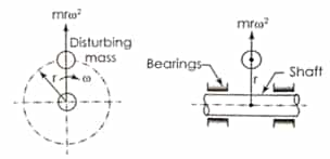 Fig.1: Single Unbalanced Rotating Mass
During the rotation of shaft, a dynamic force (centrifugal force) equal to mrω2 acts in a radially outward direction as shown in the above figure.
This unbalanced force results in increase in load on the bearings, increased bending moment on the shaft and vibrations of the system.
This dynamic force can be balanced by either of the following two methods.
- Balancing by single mass rotating in the same plane (Internal balancing)
- Balancing by two masses rotating in two different planes (External balancing)
3.1 Balancing by single mass rotating in the same plane (Internal balancing)
To balance the single rotating mass a counter mass or balancing mass ‘mb’ is placed in the plane of rotation of the disturbing mass at a radius ‘rb’ and exactly opposite to it, such that the centrifugal force due to the two masses are equal and opposite.
Mathematically,
mrω2 = mbrbω2 or mr = mbrb
This balancing of a disturbing mas by a single balancing mass in the same plane is known as Internal balancing.
3.2 Balancing by two masses rotating in different planes (External balancing):
If the balancing mass cannot be placed in the plane of rotation of the disturbing mass, then it is not possible to balance the disturbing mass by a single balancing mass.
If a single balancing mass is placed in a plane parallel to the plane of rotation of disturbing mass, the dynamic force (centrifugal force) can be balanced. However, this arrangement will introduce an unbalanced couple.
To achieve the complete balancing of the system, at least two balancing masses are required to be placed in two planes parallel to the plane of disturbing mass.
To achieve the complete balancing, two balancing masses ‘mb1’ and ‘mb2’ are placed in two different planes parallel to the plane of rotation of the disturbing mass in such a way that, they satisfy the following two conditions:
- The resultant dynamic force acting on the shaft must be equal to zero. For this, the line of action of three dynamic forces must be the same. This is the condition for static balancing.
- The resultant couple due to dynamic forces acting on the shaft must be equal to zero. In other words, the algebraic sum of the moments due to dynamic forces about any point in the plane must be zero. This is the condition for dynamic balancing.
- BALANCING OF SEVERAL MASSES ROTATING IN SAME PLANE
If the combined mass centre of the system lies on the rotational axis then it is called as in static balance.
Consider masses attached in the same plane. Due to rotation, unbalanced force is mrω2 in each mass
 Fig. 2: Balancing of several masses rotating in same plane
Total unbalance force
F = m1r1ω2 + m2r2ω2 + m3r3ω2
Here all forces are in same plane. Place another mass mc at rc with θc angle with respect to m1, such that resultant force becomes zero.
⇒ F + mcrcω2 = 0
⇒ ∑mrω2 + mcrcω2 = 0
⇒ ∑mr + mcrc = 0
The above equation can be solved either mathematically or graphically.
Mathematical Solution
Divide each force into its x and y components,
i.e. ∑ mrcosθ + mcrccos θc = 0 ⇒ mcrc cosθc = –∑mrcosθ
and ∑ mrsinθ + mcrcsin θc = 0 ⇒ mcrcsin θc = –∑mrsinθ

- BALANCING OF SEVERAL MASSES ROTATING IN DIFFERENT PLANE
Let there be a rotor revolving with a uniform angular velocity ω.m1 m2 and m3 are the masses attached to the rotor at radii r1, r2 and r3 respectively. The masses m1, m2 and m3 rotate in planes 1, 2 and 3 respectively. Choose a Reference plane at O so that the distances of the planes 1, 2 and 3 from O are l1, l2 and l3 respectively.
Fig. 3: (a) Balancing of several masses rotating in same plane,
(b) System with counter mass/balancing mass,
(c) Moment Polygon, (d) Force Polygon
For complete balancing of the rotor, the resultant force and the resultant couple, both should be zero.
- BALANCING OF RECIPROCATING MASS
Almost all IC engines use reciprocating engines (slider-crank mechanism), it would produce reciprocating unbalance force.
Since acceleration in reciprocating engine is,
![]()
Inertia force produced due to this acceleration,
![]()
Here FP = mrω2cosθ is primary unbalanced force acting along line of a stroke of the cylinder. It is due to SHM of parts. Maximum value of the primary force mrω2.
Here

FS is secondary unbalanced force also acting along line of a stroke of the cylinder. It is due to obliquity of arrangement.
6.1 Partial balancing:
To minimize the effect of the unbalanced force, a compromise is, usually, made i.e. 2/3 of the reciprocating mass is balanced (or a value between one-half and three quarters). If c is fraction of the reciprocating mass that balanced, then
Primary force balanced by the mass = cmrω2cosθ
Primary force unbalanced by the mass = (1 – c)cmrω2cosθ
Unbalanced vertical force component = cmrω2sinθ
Resultant unbalanced force at any instant R
![]()
7. EFFECT OF PARTIAL BALANCING OF LOCOMOTIVES
In partial balancing of reciprocating engine there are two unbalanced forces acting on engine.
- Unbalanced force along the line of stroke FH.
- Unbalanced force perpendicular to the line of stoke Fv.
The effect of FH is to produce the variation of Tractive Force along the line of stroke and couple of such force is known as Swaying Couple.
The effect FV, is to produce the variation of pressure on the rails which cause hammering action on the rails known as hammer blow.
7.1 Variation of tractive force (FT):
A variation in the attractive force (effort) of an engine is caused by the unbalanced portion of the primary force which acts along the line of stroke of a locomotive engine.
The tractive force is maximum or minimum when
θ = 135° or 315°

7.2 Swaying Couple (Cs):
Unbalanced primary forces along the lines of stroke are separated by a distance apart and thus, constitute a couple. This tends to make the leading wheels sway from side to side.

Fig.4: Swaying Couple
The swaying couple tends to sway the engine alternately in clockwise and anticlockwise direction about vertical axis.
Swaying couple = moments of forces about the engine centre line
![]()
The swaying couple is maximum or minimum when
θ = 45° or 225°

8. Hammer Blow:
The unbalanced force perpendicular to line of stroke produces the variation of pressure on the rails which causes hammering action on the rails which is called as hammer blow.
We know that unbalanced force along the perpendicular to the line of stroke due to balancing mass mb at radius rb is mbω2rb sin θ. This force is maximum when sinθ is unity i.e., when θ = 90° or 270°, Therefore FVU(max) = mbω2rb.
You can avail of BYJU’S Exam Prep Online classroom program for all AE & JE Exams:
BYJU’S Exam Prep Online Classroom Program for AE & JE Exams (12+ Structured LIVE Courses)
You can avail of BYJU’S Exam Prep Test series specially designed for all AE & JE Exams:
BYJU’S Exam Prep Test Series AE & JE Get Unlimited Access to all (160+ Mock Tests)
Thanks
Team BYJU’S Exam Prep
Download BYJU’S Exam Prep APP, for the best Exam Preparation, Free Mock tests, Live Classes.


Comments
write a comment