Moment Distribution Method
Introduction
- The moment distribution method is a structural analysis method for statically indeterminate beams and frames developed by Hardy Cross.
- The method only accounts for flexural effects and ignores axial and shear effects.
- The moment distribution method falls into the category of displacement method of structural analysis.
- In the slope deflection method, the end moments are computed using the slopes and deflection at the ends. Contrarily in the moment distribution method, as a first step the slopes at the ends are made zero. This is done by fixing the joints.
In the moment distribution method, every joint of the structure to be analysed is fixed so as to develop the fixed-end moments. Then each fixed joint is sequentially released and the fixed-end moments (which by the time of release are not in equilibrium) are distributed to adjacent members until equilibrium is achieved. The moment distribution method in mathematical terms can be demonstrated as the process of solving a set of simultaneous equations by means of iteration.
Important Points
- When the member is fixed at one end and a moment is applied at the other end which is simply supported or hinged, the moment induced at the fixed end is one half of the applied moment. The induced moment at the fixed end is in the same direction as the applied moment.
- If a moment is applied in a stiff joint of a structure, the moment is resisted by various members in proportion to their respective stiffnesses (i.e., moment of inertia divided by the length). If the stiffness of the member is more; then it resists more bending moment and it absorbs a greater proportion of the applied moment.
- While distributing the moments in a rigid joint, if one end of the member is not restrained then its stiffness should be multiplied by (3/4).
- In a fixed beam, if the support settles/subsides/sinks by an amount Δ, the moment required to make the ends horizontal is 6EIΔ/l2
Basic Definition
- Stiffness: Rotational stiffness can be defined as the moment required to rotate through a unit angle (radian) without the translation of either end.

Where, K = Stiffness
F = Force required to produce deflection Δ
M = Moment required to produce rotation θ.
- Stiffness Factor:
(i) It is the moment that must be applied at one end of a constant section member (which is unyielding supports at both ends) to produce a unit rotation of that end when the other end is fixed
, i.e. k = 4EI/l.
Where K = Stiffness of BA at joint B. When the farther end is fixed.
El = Flexural rigidity
L = Length of the beam
M = Moment at B.
(ii) It is the moment required to rotate the near end of a prismatic member through a unit angle without translation, the far end being hinged is k = 3EI/l.

- Carry Over Factor:
It is the ratio of the induced moment to the applied moment. The carry-over factor is always (1/2) for members of the constant moment of inertia (prismatic section). If the end is hinged/pin-connected, the carry-over factor is zero. It should be mentioned here that carry over factors values differ for non-prismatic members. For non-prismatic beams (beams with variable moment of inertia); the carryover factor is not half and is different for both ends.Carryover factor =
COF may greater than, equal to or less than 1.
Standard Cases:
(ii) COF = 0
- Distribution Factors:


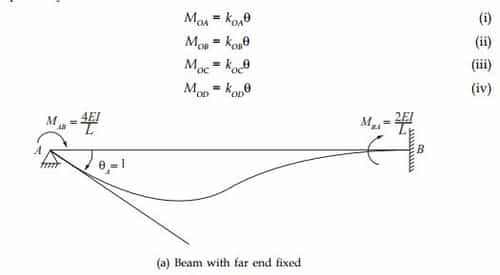
Consider a frame with members OA, OB, OC and OD rigidly connected at O as shown below. Let M be the applied moment at joint O in the clockwise direction. Let the joint rotate through an angle θ. The members OA, OB, OC and OD also rotate by the same angle θ

Let kOA , kOB, kOC and kOD be the stiffness values of the members OA, OB, OC and OD respectively; then

5. Relative Stiffness
(i) When farther end is fixed
Relative stiffness for member ![]()
(ii) When the farther end is hinged
Relative stiffness for member ![]()

Stiffness of OA ![]()
Stiffness of OB ![]()
Stiffness of OC ![]()
Stiffness of OD = 0
SIGN CONVENTION
Clockwise moments are considered positive and anticlockwise moments negative
+ve → Sagging
–ve → Hogging
and All clockwise moment → +ve
and All Anti clockwise moment → –ve
Span length is l


Example
Draw the bending moment diagram for the continuous beam ABCD loaded as shown below. The relative moment of inertia of each span of the beam is also shown in the figure.

Solution
Note that joint C is hinged and hence stiffness factor BC gets modified. Assuming that the supports are locked, calculate fixed end moments. They are

In the next step calculate stiffness and distribution factors


Now all the calculations are shown below

Computation

Bending Moment Diagram
Note: This problem has also been solved by the slope-deflection method
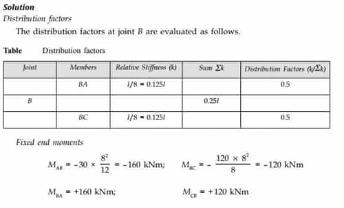
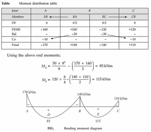
Example 2
Analyse the continuous beam by the moment distribution method. Draw the shear force diagram and bending moment diagram.


You can avail of BYJU’S Exam Prep Online classroom program for all AE & JE Exams:
BYJU’S Exam Prep Online Classroom Program for AE & JE Exams (12+ Structured LIVE Courses)
You can avail of BYJU’S Exam Prep Test series specially designed for all AE & JE Exams:
BYJU’S Exam Prep Test Series AE & JE Get Unlimited Access to all (160+ Mock Tests)
Thanks
Team BYJU’S Exam Prep
Download BYJU’S Exam Prep APP, for the best Exam Preparation, Free Mock tests, Live Classes.


Comments
write a comment