Trusses are used commonly in Steel buildings and bridges. The article contains fundamental notes on "Analysis of Trusses" topic of "Structure Analysis" subject. Also useful for the preparation of various upcoming exams like GATE Civil Engineering(CE)/ IES/ BARC/SSC-JE /State Engineering Services examinations and other important upcoming competitive exams.
Analysis of Trusses
Trusses are used commonly in Steel buildings and bridges.

Definition: A truss is a structure that consists of
- All straight members
- Connected together with pin joints
- Connected only at the ends of the members
- All external forces (loads & reactions) must be applied only at the joints.
- Trusses are assumed to be of negligible weight (compared to the loads they carry)
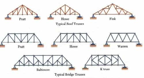
Types of Trusses
Degree of Static Indeterminacy
- DS = m+re – 2j where, DS = Degree of static indeterminacy m = Number of members, re = Total external reactions, j = Total number of joints
- DS = 0 ⇒ Truss is determinate
If Dse = + 1 & Dsi = –1 then DS = 0 at specified point. - DS > 0 ⇒ Truss is indeterminate or dedundant.
Truss Analysis: Method of Joints
- Conditions of equilibrium are satisfied for the forces at each joint
- Equilibrium of concurrent forces at each joint
- Only two independent equilibrium equations are involved
Steps of Analysis
- Draw Free Body Diagram of Truss
- Determine external reactions by applying equilibrium equations to the whole truss
- Perform the force analysis of the remainder of the truss by Method of Joints
Example 1
Determine the force in each member of the loaded truss by Method of Joints

Solution


Truss Member Carrying Zero forces
(i) M1, M2, M3 meet at a joint M1 & M2 are collinear ⇒ M3 carries zero force where M1, M2, M3 represents member.

(ii) M1 & M2 are non collinear and Fext = 0 ⇒ M1 & M2 carries zero force.


- If only two non-collinear members form a truss joint and no external load or support reaction is applied to the joint, the two members must be zero force members
- If three members form a truss joint for which two of the members are collinear, the third member is a zero-force member provided no external force or support reaction is applied to the joint.

Method of Section
- It can be used to determine three unknown member forces per FBD since all three equilibrium equations can be used
- Equilibrium under non-concurrent force system
- Not more than 3 members whose forces are unknown should be cut in a single section since we have only 3 independent equilibrium equations

Principle:
- If a body is in equilibrium, then any part of the body is also in equilibrium.
- Forces in few particular member can be directly found out quickly without solving each joint of the truss sequentially
- Method of Sections and Method of Joints can be conveniently combined
- A section need not be straight.
- More than one section can be used to solve a given problem
Example 2
The truss in Fig given below is pinned to the wall at point F, and supported by a roller at point C. Calculate the force (tension or compression) in members BC, BE, and DE.

Solution

ΣME=0
5FBC=6(80)+2(60)
FBC=120 kN compression
ΣMB=0
5FDE=4(80)
FDE=64 kN Tension
Indeterminate Truss
(i) Final force in the truss member

sign convn → +ve for tension, –ve for compression
where,
S = Final force in the truss member
K = Force in the member when unit load is applied in the redundant member
L = Length of the member
A = Area of the member
E = Modulus of elasticity
P = Force in the member when truss become determinate after removing one of the member.
P = Zero for redundant member.
Lack of Fit in Truss
![]()
Q = Force induce in the member due to that member which is 'Δ' too short or 'Δ' too long is pulled by force 'X'.
Deflection of Truss

Where, yC = Deflection of truss due to effect of loading & temp. both.
If effect of temperature is neglected then
![]()
α = Coefficient of thermal expansion
T = Change in temperature
T = +ve it temperature is increased
T = -ve it temperature is decreased
P & K have same meaning as mentioned above.
You can avail of Online Classroom Program for all AE & JE Exams:
Online Classroom Program for AE & JE Exams (12+ Structured LIVE Courses and 160+ Mock Tests)
You can avail of BYJU'S Exam Prep Test Series specially designed for all AE & JE Exams:
BYJU'S Exam Prep Test Series AE & JE (160+ Mock Tests)

Thanks,
Team BYJU'S Exam Prep
Sahi Prep Hai to Life Set Hai !!!
Download BYJU'S Exam Prep APP , for best Exam Preparation , Free Mock Test, Live Classes
Sahi Prep Hai To Life Set Hai.


Comments
write a comment