Earth Pressure Theories
Rankine's Earth Pressure Theory
The Rankine's theory assumes that there is no wall friction (δ = 0), the ground and failure surfaces are straight planes, and that the resultant force acts parallel to the backfill slope.
In case of retaining structures, the earth retained may be filled up earth or natural soil. These backfill materials may exert certain lateral pressure on the wall. If the wall is rigid and does not move with the
pressure exerted on the wall, the soil behind the wall will be in a state of elastic equilibrium. Consider the prismatic element E in the backfill at depth, z, as shown in Fig.


Earth Pressure at Rest

Rankine's Earth Pressure Against A Vertical Section With The Surface Horizontal With Cohesionless Backfill
Active earth pressure:

Rankine's active earth pressure in the cohesionless soil

Passive earth pressure:

Rankine's passive earth pressure in cohesionless soil

Rankine's active earth pressure with a sloping cohesionless backfill surface
As in the case of horizontal backfill, active case of plastic equilibrium can be developed in the backfill by rotating the wall about A away from the backfill. Let AC be the plane of rupture and the soil in the wedge ABC is in the state of plastic equilibrium.


Rankine's active earth pressures of cohesive soils with horizontal backfill on smooth vertical walls

Coulomb's Wedge Theory

Some Graphical solutions for lateral Earth Pressure are
- Culman's solution
- The trial wedge method
- The logarithmic spiral
Stability Analysis of Slopes
The quantitative determination of the stability of slopes is necessary in a number of engineering activities, such as:
(a) the design of earth dams and embankments,
(b) the analysis of stability of natural slopes,
(c) analysis of the stability of excavated slopes,
(d) analysis of the deepseated failure of foundations and retaining walls.
Quite a number of techniques are available for these analyses

FACTORS OF SAFETY
The factor of safety is commonly thought of as the ratio of the maximum load or stress that a soil can sustain to the actual load or stress that is applied. Referring to Fig. given below the factor of safety F, with respect to strength, may be expressed as follows:

![]()
where τff is the maximum shear stress that the soil can sustain at the value of normal stress of σn , τ is the actual shear stress applied to the soil.
Above equation may be expressed in a slightly different form as follows:
![]()
Two other factors of safety which are occasionally used are the factor of safety with respect to cohesion, Fc, and the factor of safety with respect to friction, Fφ.
The factor of safety with respect to cohesion may be defined as the ratio between the actual cohesion and the cohesion required for stability when the frictional component of strength is fully mobilised. This may be expressed as follows:
![]()
The factor of safety with respect to friction, Fφ, may be defined as the ratio of the tangent of the angle of shearing resistance of the soil to the tangent of the mobilised angle of shearing resistance of the soil when the cohesive component of strength is fully mobilised.

A further factor of safety which is sometimes used is FH, the factor of safety with respect to height. This is defined as the ratio between the maximum height of a slope to the actual height
of a slope and may be expressed as follows:
![]()
where, Cm = Mobilized Cohesion
∅m = Mobilized Friction Angle
 and
and 
Factor of Safety w.r.t. Cohesion (fC)
 and
and 
where, Hc = Critical depth
H = Actual depth

Stability Analysis of Infinite Slopes
(i) Cohesionless dry soil/dry sand
![]()
![]()
![]()

where,
τ = Developed shear stress or mobilized shear stress
σn = Normal stress.

where,
Fs = Factor of safety against sliding
![]()
- For safety of Slopes
![]()
↓
![]()

(ii) Seepage taking place and the water table is parallel to the slope in Cohesionless Soil

h = Height of water table above the failure surface.

φ’ is effective friction angle
γ-avg. total unit weight of soil above the slip surface upto ground level.

(iii) If water table is at ground level: i.e.,
h = z
![]()
![]()
(iv) Infinite Slope of Purely Cohesive Soil
![]()
Here H = z = depth of slice/cut.
At Critical Stage Fc =1
![]()
where, Sη = Stability Number.
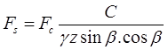
(v) C-∅ Soil in Infinite Slope
![]()
(vi) Taylor's stability no.
 (for cohesive soil)
Max. theoretical value of stability no. = 0.5
Max. practical value is = 0.261
![]() (for C-∅ soils)
(for C-∅ soils)
Stability Analysis of Finite Slopes
(i) Fellinious Method
(For Purely Cohesive Soil)
A. where, F = Factor of safety
r = Radius of rupture curve
I = Length of rupture curve

B. 

F = Factor of safety it tension cracks has developed.

(ii) Swedish Circle Method

where, F = Factor of safety

(iii) Friction Circle Method


(iv) Taylor's Stability Method (C-∅ soil)

In case of submerged slope γ should be used instead of γ and if slope is saturated by capillary flow they γsat should be used instead of γ.
 where ∅w = weight friction angle.
You can avail Online Classroom Program for all AE & JE Exams:
Online Classroom Program for AE & JE Exams (12+ Structured LIVE Courses and 160+ Mock Tests)
If you are preparing for ESE/ GATE or other PSU Exams (Civil Engineering), then avail Online Classroom Program for ESE and GATE CE:
Online Classroom Program for ESE/GATE CE(20+ Courses and 180+ Mock Tests)
You can avail of BYJU'S Exam Prep Test Series specially designed for all AE & JE Exams:
BYJU'S Exam Prep Test Series AE & JE (160+ Mock Tests)
You can avail of BYJU'S Exam Prep Test Series specially designed for all Civil Engineering Exams:
BYJU'S Exam Prep Test Series ESE/GATE CE (180+ Mock Tests)
Thanks
Sahi Prep Hai To Life Set Hai.


Comments
write a comment