Seepage & Permeability of Soil
Seepage Pressure and Seepage Force
Seepage pressure is exerted by the water on the soil due to friction drag. This drag force/seepage force always acts in the direction of flow.
The seepage pressure is given by
PS = hγω where, Ps = Seepage pressure
γω = 9.81 kN/m3
Here, h = head loss and z = length
(ii) FS = hAγω where, Fs = Seepage force
(iii) ![]() where, fs = Seepage force per unit volume.
where, fs = Seepage force per unit volume.
i = h/z where, I = Hydraulic gradient.
Quick Sand Condition
It is condition but not the type of sand in which the net effective vertical stress becomes zero, when seepage occurs vertically up through the sands/cohesionless soils.
Net effective vertical stress = 0
![]()
where, ic = Critical hydraulic gradient.
2.65 ≤ G≤ 2.70 0.65 ≤ e ≤ 0.70
- To Avoid Floating Condition
![]() and
and
![]()
Laplace Equation of Two Dimensional Flow and Flow Net: Graphical Solution of Laplace Equation
(i) 
where, ∅ = Potential function = kH
H = Total head and k = Coefficient of permeability
(ii) ![]()
… 2D Laplace equation for Homogeneous soil.
where, ∅ = kX H and ∅ = ky H for Isotropic soil, kx= ky
Seepage discharge (q)

where, h = hydraulic head or head difference between upstream and downstream level or head loss through the soil.
- Shape factor =

where, Nf = Total number of flow channels
![]() = Total number of flow lines.
= Total number of flow lines.
where, Nd = Total number equipotential drops.
![]() = Total number equipotential lines.
= Total number equipotential lines.
- Hydrostatic pressure = U =
where, U = Pore pressure hw = Pressure head
hw = Hydrostatic head – Potential head
- Seepage Pressure
Ps = h'γw where, 

- Exit gradient,

where, size of exit flow field is b x b.
and  is equipotential drop.
Phreatic Line
It is top flow line which follows the path of base parabola. It is a stream line. The pressure on this line is atmospheric (zero) and below this line pressure is hydrostatic.
(a) Phreatic Line with Filter


Phreatic line (Top flow line).
↓
Follows the path of base parabola
CF = Radius of circular arc = ![]()
C = Entry point of base parabola
F = Junction of permeable and impermeable surface
S = Distance between focus and directrix
= Focal length.
FH = S
(i) q = ks where, q = Discharge through unit length of dam.
(ii) ![]()
(iii) 
(b) Phreatic Line without Filter

(i) For ∝ < 30°
q = k a sin2 ∝
![]()
(ii) For ∝ > 30°
q = k a sin ∝ tan ∝ and
![]()
Permeability
Permeability of Soil
The permeability of a soil is a property which describes quantitatively, the ease with which water flows through that soil.
Darcy's Law : Darcy established that the flow occurring per unit time is directly proportional to the head causing flow and the area of cross-section of the soil sample but is inversely proportional to the length of the sample.
(i) Rate of flow (q)


Where, q = rate of flow in m3/sec.
K = Coefficient of permeability in m/s
I = Hydraulic gradient
A = Area of cross-section of sample
![]()
where, HL = Head loss = (H1 – H2)
![]()
(ii) Seepage velocity

where, Vs = Seepage velocity (m/sec)
n = Porosity & V = discharge velocity (m/s)
(iii) Coefficient of percolation
![]()
where, KP = coefficient of percolation and n = Porosity.
Constant Head Permeability Test

where, Q = Volume of water collected in time t in m3.
Constant Head Permeability test is useful for coarse grain soil and it is a laboratory method.

Falling Head Permeability Test or Variable Head Permeability Test

a = Area of tube in m2
A = Area of sample in m2
t = time in 'sec'
L = length in 'm'
h1 = level of upstream edge at t = 0
h2 = level of upstream edge after 't'.

Konzey-Karman Equation

Where, C = Shape coefficient, ∼5mm for spherical particle
S = Specific surface area = ![]()
For spherical particle.

R = Radius of spherical particle.

When particles are not spherical and of variable size. If these particles passes through sieve of size 'a' and retain on sieve of size 'n'.
e = void ratio
μ = dynamic viscosity, in (N-s/m2)
![]() = unit weight of water in kN/m3
= unit weight of water in kN/m3

Allen Hazen Equation
![]()
Where, D10 = Effective size in cm. k is in cm/s C = 100 to 150
Loudens Equation
![]()
Where, S = Specific surface area
n = Porosity.
a and b are constant.
Consolidation equation
![]()
Where, Cv = Coefficient of consolidation in cm2/sec
mv = Coefficient of volume Compressibility in cm2/N
Capillary Permeability Test

![]()
where, S = Degree of saturation
K = Coefficient of permeability of partially saturated soil.
![]()
where hc = remains constant (but not known as depends upon soil)
![]() = head under first set of observation,
= head under first set of observation,
n = porosity, hc = capillary height
Another set of data gives,

![]() = head under second set of observation
= head under second set of observation
- For S = 100%, K = maximum. Also, ku ∝ S.
Permeability of a stratified soil
(i) Average permeability of the soil in which flow is parallel to bedding plane,

![]()

(ii) Average permeability of soil in which flow is perpendicular to bedding plane.
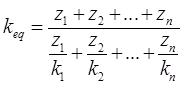
![]()

(iii) For 2-D flow in x and z direction
![]()
(iv) For 3-D flow in x, y and z direction ![]()
Coefficient of absolute permeability (k0)


Comments
write a comment