The objectives of compaction are:
- To increase soil shear strength and therefore its bearing capacity.
- To reduce subsequent settlement under working loads.
- To reduce soil permeability making it more difficult for water to flow through.
Laboratory Compaction
The variation in compaction with water content and compactive effort is first determined in the laboratory. There are several tests with standard procedures such as:
- Indian Standard Light Compaction Test (similar to Standard Proctor Test/Light Compaction Test)
- Indian Standard Heavy Compaction Test (similar to Modified Proctor Test/Heavy Compaction Test)

Indian Standard Light Compaction Test
Soil is compacted into a 1000 cm3 mould in 3 equal layers, each layer receiving 25 blows of a 2.6 kg rammer dropped from a height of 310 mm above the soil. The compaction is repeated at various moisture contents.
Indian Standard Heavy Compaction Test
It was found that the Light Compaction Test (Standard Test) could not reproduce the densities measured in the field under heavier loading conditions, and this led to the development of the Heavy Compaction Test (Modified Test). The equipment and procedure are essentially the same as that used for the Standard Test except that the soil is compacted in 5 layers, each layer also receiving 25 blows. The same mould is also used. To provide the increased compactive effort, a heavier rammer of 4.9 kg and a greater drop height of 450 mm are used.
Compactive energy applied per unit


- The ratio of total energy given in heavy compaction test to that given in light compaction test
![]()
Dry Density - Water Content Relationship
- To assess the degree of compaction, it is necessary to use the dry unit weight, which is an indicator of compactness of solid soil particles in a given volume.
- Laboratory testing is meant to establish the maximum dry density that can be attained for a given soil with a standard amount of compactive effort.
In the test, the dry density cannot be determined directly, and as such the bulk density and the moisture content are obtained first to calculate the dry density as
![]() ,
,
where γd = bulk density, and w = water content.
- A series of samples of the soil are compacted at different water contents, and a curve is drawn with axes of dry density and water content. The resulting plot usually has a distinct peak as shown. Such inverted “V” curves are obtained for cohesive soils (or soils with fines), and are known as compaction curves.

- Dry density can be related to water content and degree of saturation (S) as

Thus, it can be visualized that an increase of dry density means a decrease of voids ratio and a more compact soil.
Similarly, dry density can be related to percentage air voids (na) as
Relation between moisture content and dry unit weight for a saturated soil is the zero air-voids line. It is not feasible to expel air completely by compaction, no matter how much compactive effort is used and in whatever manner.

Effect of Increasing Water Content
- As water is added to a soil at low moisture contents, it becomes easier for the particles to move past one another during the application of compacting force. The particles come closer, the voids are reduced and this causes the dry density to increase. As the water content increases, the soil particles develop larger water films around them.
- This increase in dry density continues till a stage is reached where the water starts occupying the space that could have been occupied by the soil grains. Thus the water at this stage hinders the closer packing of grains and reduces the dry unit weight. The maximum dry density (MDD) occurs at an optimum water content (OMC), and their values can be obtained from the plot.
Effect of Increasing Compactive Effort
- The effect of increasing compactive effort is shown. Different curves are obtained for different compactive efforts. A greater compactive effort reduces the optimum moisture content and increases the maximum dry density.

- An increase in compactive effort produces a very large increase in dry density for soil when it is compacted at water contents drier than the optimum moisture content.It should be noted that for moisture contents greater than the optimum, the use of heavier compaction effort will have only a small effect on increasing dry unit weights.
It can be seen that the compaction curve is not a unique soil characteristic. It depends on the compaction effort. For this reason, it is important to specify the compaction procedure (light or heavy) when giving values of MDD and OMC.
Factors Affecting Compaction
The factors that influence the achieved degree of compaction in the laboratory are:
- Plasticity of the soil
- Water content
- Compactive effort
Compaction of Cohesionless Soils
For cohesionless soils (or soils without any fines), the standard compaction tests are difficult to perform. For compaction, application of vibrations is the most effective method. Watering is another method. To achieve maximum dry density, they can be compacted either in a dry state or in a saturated state.
- For these soil types, it is usual to specify a magnitude of relative density (ID) that must be achieved. If e is the current void ratio or gd is the current dry density, the relative density is usually defined in percentage as
or
where emax and emin are the maximum and minimum void ratios that can be determined from standard tests in the laboratory, and gdmin and gdmax are the respective minimum and maximum dry densities
On the basis of relative density, sands and gravels can be grouped into different categories:
Relative density (%) Classification
< 15 Very loose
15-35 Loose
35-65 Medium
65-85 Dense
> 85 Very dense
It is not possible to determine the dry density from the value of the relative density. The reason is that the values of the maximum and minimum dry densities (or void ratios) depend on the gradation and angularity of the soil grains.
Engineering Behaviour of Compacted Soils
The water content of a compacted soil is expressed with reference to the OMC. Thus, soils are said to be compacted dry of optimum or wet of optimum (i.e. on the dry side or wet side of OMC). The structure of a compacted soil is not similar on both sides even when the dry density is the same, and this difference has a strong influence on the engineering characteristics.
- Soil Structure
For a given compactive effort, soils have a flocculated structure on the dry side (i.e. soil particles are oriented randomly), whereas they have a dispersed structure on the wet side (i.e. particles are more oriented in a parallel arrangement perpendicular to the direction of applied stress). This is due to the well-developed adsorbed water layer (water film) surrounding each particle on the wet side. - Swelling
Due to a higher water deficiency and partially developed water films in the dry side, when given access to water, the soil will soak in much more water and then swell more. - Shrinkage
During drying, soils compacted in the wet side tend to show more shrinkage than those compacted in the dry side. In the wet side, the more orderly orientation of particles allows them to pack more efficiently. - Construction Pore Water Pressure
The compaction of man-made deposits proceeds layer by layer, and pore water pressures are induced in the previous layers. Soils compacted wet of optimum will have higher pore water pressures compared to soils compacted dry of optimum, which have initially negative pore water pressure. - Permeability
The randomly oriented soil in the dry side exhibits the same permeability in all directions, whereas the dispersed soil in the wet side is more permeable along particle orientation than across particle orientation. - Compressibility

At low applied stresses, the dry compacted soil is less compressible on account of its truss-like arrangement of particles whereas the wet compacted soil is more compressible.
The stress-strain curve of the dry compacted soil rises to a peak and drops down when the flocculated structure collapses. At high applied stresses, the initially flocculated and the initially dispersed soil samples will have similar structures, and they exhibit similar compressibility and strength.
Some extra details about compaction -


- Coarse grained well graded – Higher γd
- In clays with higher plasticity - γd decrease
- V shape due to bulking of pure sand
Stress Distribution in The Soil
At a point within a soil mass, stresses will be developed as a result of the soil lying above the point and by any structural or other loading imposed onto that soil mass .
Stress in the soil may be caused by:
- Self weight of soil
- Applied load on soil

Finitely loaded area
If the surface loading area is finite (point, circular, strip, rectangular, square), the vertical stress increment in the subsoil decreases with increase in the depth and the distance from the surface loading area.
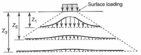
Methods have been developed to estimate the vertical stress increment in sub-soil considering the shape of the surface loading area.
Boussinesq's Theory
Point Load
A point load or a Concentrated load is, strictly speaking, hypothetical in nature, consideration of it serves a useful purpose in arriving at the solutions for more complex loadings in practice.
Assumptions made by Boussinesq.
(i) The soil medium is an elastic, homogeneous, isotropic and semi-infinite medium, which infinitely in all directions from a level surface.
(ii) The medium obeys Hookes law.
(iii) The self-weight of the soil is ignored.
(iv) The soil is initially unstressed
(v) The change in volume of the soil upon application of the loads on to it is neglected.
(vi) The top surface of the medium is free of shear stress and is subjected to only the point load at a specified location.
(vii) Continuity of stress is considered to exist in the medium.
(viii) The stresses are distributed symmetrically with respect to z axis.

The Boussinesq equations are as follows :


This intensity of vertical stress directly below the point load, on its axis of loading (r=0) is given by:
![]()
The vertical stress on a horizontal plane at depth „Z‟ is given by
![]()
Z being a specified depth.

Boussinesq's Result


Westergaard's Theory
(i) 
(ii) 
(iii) ![]()
Westergaard's Results
(i) Vertical Stresss due to Live Loads

where, σz = Vertical stress of any point having coordinate (x, z)
Load intensity = q'/m
at X = 0


(ii) Vertical Stress due to Strip Loading

where, σz = Vertical stress at point 'p'

(iii) 

(iv) Vertical stress below uniform load acting on a circular area.
σz = q(1-cos3 θ)
where, 

Newmark's Chart Method (Uniform Load on irregular Areas)
- Newmark (1942) constructed an influence chart, based on the Boussinesq solution to determine the vertical stress increase at any point below an area of any shape carrying uniform pressure.
- This method is applicable to semi-infinite, homogeneous, isotropic and elastic soil mass. It is not applicable for layered structures.
- The greatest advantage of this method is that it can be applied to a uniformly distributed area of an irregular shape.
- The chart consists of influence areas that have an influence value of 0.005 per unit pressure.
- Position the loaded area on the chart such that the point at which the vertical stress required is at the centre of the chart.
- Newmark's chart is made of concentric circles and radial lines. Normally there are 10 concentric circles and 20 radial lines.
No. of concentric circle = 10
No. of radial lines = 20
Influence of area (1) = Influence of area (2) = Influence of area (3)
Influence of each area
![]()
σz = 0.005qNA
where, NA = Total number of sectorial area of Newmark's chart.

Approximate method
(i) Equivalent Load Method
![]()
where,
![]()

(ii) Trapezoidal Method
σz at depth 
For 1H : 1 V


(iii) Stress Isobar Method:
Area bounded by 0.2q stress isobar is considered to be stressed by vertical stress on loading.
0.2q = 20% Stress Isobar


You can avail of BYJU’S Exam Prep Online classroom program for all AE & JE Exams:
BYJU’S Exam Prep Online Classroom Program for AE & JE Exams (12+ Structured LIVE Courses)
You can avail of BYJU’S Exam Prep Test series specially designed for all AE & JE Exams:
BYJU’S Exam Prep Test Series AE & JE Get Unlimited Access to all (160+ Mock Tests)
Thanks
Team BYJU’S Exam Prep
Download BYJU’S Exam Prep APP, for the best Exam Preparation, Free Mock tests, Live Classes.


Comments
write a comment