INTRODUCTION TO MICROPROCESSORS
The most important technological invention of modern times is the “microprocessor". A microprocessor is a multiple purpose programmable clock driven, register based electronic device that reads binary instructions from memory, accepts binary data as input and processing this data according to the instructions written in the memory. The microprocessor is capable of performing computing functions and making decisions to change the sequence of program execution. The microprocessor can be embedded in a larger system and can function as the CPU of a computer called a microcomputer.

Basic block diagram of a microcontroller
Here, input device is a device that transfers information from outside world to the computer for example: Key board, mouse, webcam, microphone, scanner, electronic white boards, etc. The output device transfers information from computer to the outside world like monitor, printers (all types), speakers, headphones, projector, plotter, Braille embosser, LCD projection panel, computer output microfilm (COM) etc. Memory is an electronic medium that stores binary information.
Central Processing Unit (CPU) is the heart of computer systems. The microprocessors in any microcomputer act as a CPU. The CPU can be made up with ALU + CU + Registers. Where ALU is the group of circuits that performs arithmetic and logical operations. Control Unit (CU) is a group of circuits that provide timings and signals to all the operations in the computer and controls the dataflow.
Microcontroller is a programmable device that includes microprocessor, memory and I/O signal lines on a single chip, fabricated using VLSI technology. Microcontrollers are also known as single chip microcomputers. They are mostly used to perform dedicated functions such as automatic control of equipment, machines and process in industries and consumer appliances.
Microprocessor:
A microprocessor includes ALU, register arrays and control circuits on a single chip.
Microcontroller:
A device that includes microprocessor, memory and input and output signal lines on a single chip, fabricated using VLSI technology.
System Bus:
A bus is a group of wires/lines used to transfer data (bits) between components inside a computer or between computers. In most simple form, they are communication path used to carry the signals between microprocessor and peripherals.
The system bus of a microprocessor is of three types :
- Address Bus:
- It is a group of lines that are used to send a memory address or a device address from the Microprocessor Unit (MPU) to the memory or the peripheral.
- The address bus is always unidirectional i.e. address always goes out of the microprocessor.
- If the address line are ‘n’ for an MPU then its addressing capacity is 2n.
- Data Bus:
- It is group of lines used to transfer data between the microprocessor and peripherals and/or memory.
- Data bus is always bi-directional.
- Control Bus:
- Control bus provides signals to control the flow of data.
8085 Microprocessor
It is a programmable electronics chip ( Integrated Circuit (IC) ). A single IC has computing and decision-making capabilities similar to the central processing unit of a computer. It is used in almost all types of electronics devices like mobile phones, printers, washing machines, etc. and also used in advanced applications like radars, satellites and flights.
- It has 8-bit data bus and 16-bit address bus, thus it is capable of addressing 64 KB of memory.
- It has 8 bit ALU 8 bit ALU that can perform 8-bit operations.
- Lower order address bus is multiplexed with data bus to minimize the chip size.
- The 8085 microprocessor is an 8-bit processor available as a 40-pin IC package (shown the figure below) and uses +5 V for power. It can run at a maximum frequency of 3 MHz.
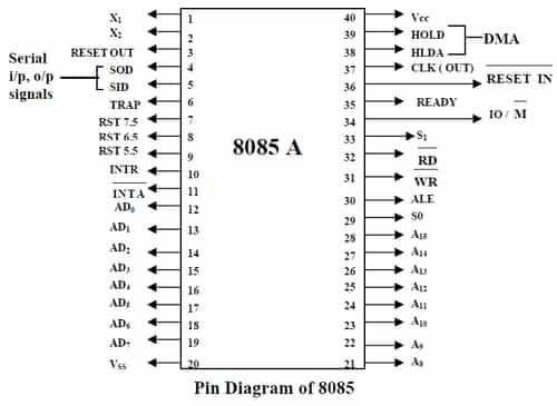
- The 8085 has extensions to support new interrupts, with three maskable interrupts (RST 7.5, RST 6.5 and RST 5.5), one non-maskable interrupt (TRAP), and one externally serviced interrupt (INTR).
- Three control signals are available on a chip:
(i) RD: it is an active low signal. Which indicates that the selected IO or Memory device is to be read and data is available on the data bus.
(ii) WR: it is an active low signal which indicates that the data on the data bus is to be written into a selected memory or IO location.
(iii) ALE: it is a +ve going pulse generated every time the 8085 begins an operation (machine cycle), which indicates that the bits on AD7-AD0 are address bits.
- Three status signals are available on a chip:
(i) IO/M: this is a status signal used to differentiate between IO and Memory operations. If it is high then IO operation and If it is low then Memory operation.
(ii) S1 and S0: status signals similar to IO/M, can identify various operations that are rarely used in the systems.


Comments
write a comment