Introduction to Brakes
A brake is a mechanical device whose function is used to absorb the kinetic energy of the system by means of friction.
Types of Brakes
(i). Mechanical Brakes: The working of these brakes is based on mechanical means such as levers, springs and pedals.
(ii) Hydraulic and pneumatic brakes: Controlling action is due to fluid pressure such as oil pressure or air pressure.
(iii). Electrical brakes: Working is based on magnetic forces and this category of brakes includes magnetic particle brakes, hysteresis brakes and eddy – current brakes.
Block brake with short shoe brake: It is combination of a simple block and rotating drum.
As the block is pressed, the drum motion is retarded due to the friction between the drum and the block. The contact angle of the block and the brake drum is generally small. If the contact angle < 45°, then pressure distribution is uniform of the drum due to braking action.

The forces acting on the brake drum,
![]()
where:
Mt = braking – torque (N-mm)
R= radius of the brake drum (mm)
μ=coefficient of friction,
N= normal reaction (N),
Based on the hinge pin location and coefficient of friction value, there are three different possibilities:
Case I: a > μc, The friction force helps to reduce the magnitude of the actuating force .
Case II: a = μc, The actuating force is zero which signifies that no external force is needed for the braking action and the brake is known a ‘self – locking’ brake.
Case III: a < μc, The actuating force becomes negative. It is serious condition which results in uncontrolled braking and grabbing.
Block brake with long shoe:

Torque is given as:
![]()
Where:
![]()
and, θ is the semi – cone angle.
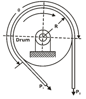
Simple band brakes:
The steel band working is is same as that of a flat belt operation with zero velocity.


Torque absorbed by the brake is given by:
![]()
Differential band brakes:
- When neither end of the steel band passes through the fulcrum of the actuating lever, the brake is called the differential band brake.
The free – body diagram of forces acting on the band and the lever is shown in figure,


For the self – locking condition:
![]()
Disk brakes: A disk brake is similar to a plate clutch with one small modification of replacement of one of the shafts by a fixed member.
Advantages of disk brakes
- Disk brake is simple to install and operate
- Disk brake has high torque transmitting capacity in small volume
- The brake can never become self – locking
Introduction of the clutch:
It is a mechanical device, which is used to connect or disconnect the source of power from the remaining parts of the power transmission system at operator's will.
Types of clutch:
(i). Positive Contact Clutches: Examples of such clutches are square jaw clutches, spiral jaw clutches and toothed clutches.
(ii). Friction Clutches: They include single and multi-plate clutches, cone clutches and centrifugal clutches.
(iii). Electromagnetic Clutches: Magnetic particle clutches, magnetic hysteresis clutches and eddy current clutches are examples of electromagnetic clutches.
(iv). Fluid Clutches: Hydraulic pressure is the means of the power transmission.
Torque transmitting capacity of single plate clutch:
A friction disk of a single plate clutch is shown in figure:

D= Outer diameter of friction disk (mm)
d = inner diameter of friction disk (mm)
P= intensity of pressure at radius (mm)
F = operating force (N)
Mt = torque transmitted by the clutch (N-mm)

The theories used to find the torque capacity of the clutch are Uniform pressure theory (UPT) and Uniform wear theory (UWT).
Uniform Pressure Theory (UPT): In case of new clutches employing a number of springs, the pressure remains constant over the entire surface area of the friction disk.

Uniform wear theory (UWT): It is assumed that the wear is uniformly distributed over the entire surface area the friction disk. When the wear is uniform:
P.r = Constant
In this case, P is inversely proportional to r. Therefore, maximum pressure occurs at the inner radius while minimum pressure at the outer periphery.
![]()
Note:
Number of disks = number of pairs of contacting surfaces + 1 = Z + 1
Suppose:
Z1= number of disks on driving shaft
Z2 = number of disks on driven shaft
Z1 +Z2 = number of pairs of contacting surfaces + 1
Number of pairs of contacting surfaces = Z1 + Z2 – 1
Cone clutches:

In case of uniform pressure theory:
![]()
In case of uniform wear theory:
![]()
where, α is the semi cone angle.
Centrifugal clutch: It consists of number of shoes on the inside of a rim of the pulley and the shoes outer surfaces are covered with a friction material. These shoes (move radially in guides) are held against the boss on the driving shaft by means of spring which causes a constant radially inward force.
the torque transmitting capacity of the clutch is given by,

Notations used
rd = radius of the drum (mm)
rg = radius of the centre of gravity of the shoe in engaged position (mm)
m= mass of each shoe
Pcf = centrifugal force (N)
Ps = spring force (N)
z= number of shoes
ω2 =running speed (rad/s)
ω1= speed at which engagement starts (rad/s).
You can avail of BYJU’S Exam Prep Online classroom program for all AE & JE Exams:
BYJU’S Exam Prep Online Classroom Program for AE & JE Exams (12+ Structured LIVE Courses)
You can avail of BYJU’S Exam Prep Test series specially designed for all AE & JE Exams:
BYJU’S Exam Prep Test Series AE & JE Get Unlimited Access to all (160+ Mock Tests)
Thanks
Team BYJU’S Exam Prep
Download BYJU’S Exam Prep APP, for the best Exam Preparation, Free Mock tests, Live Classes.


Comments
write a comment