In this article, you will find the complete study notes on Transformer.
- A basic transformer consists of two separate windings of insulated wires wound around a common iron core.
- The power source or supply is hooked to the primary winding, the load to be served is hooked to the secondary winding.
- Primary windings, connected to the alternating voltage source, and Secondary windings, connected to the load. Iron core used to link the flux in both windings.
- When the primary winding is energized an electromagnetic field builds up and then collapses in the iron core, this field cuts through the secondary coil winding inducing power to the load hooked to the secondary.
- This power build up and collapse is called magnetic flux and occurs at a frequency of sixty times a second (60 Hz) in an a.c. circuit.
- Unlike in rotating machines, there is no energy conversion.
- Transformers are based on the principle of “mutual-induction.” When current flows through a wire a magnetic field is produced.
- When a conductor passes through a magnetic field, a current flow will be induced through the wire.
- The method of transferring electrical energy by a transformer is done indirectly. Electrical energy is first converted into magnetic energy, then reconverted back into electrical energy at a different voltage and ampacity. Magnetism and electricity are closely related.

- By altering the number of windings on the primary and secondary, we can alter the amount of volts and amps between the source and the load.
- The current in the secondary coil always changes by the inverse of the ratio by which the voltage changes.
- If the voltage is raised to n times its original value by the transformer, the current in the secondary coil will be reduced to one- n th the value of the current in the primary coil.
- The rms value of induced emf can be find as:
- Primary induced emf E1 = 4.44 f N1 φm volt
- Secondary induced emf E2 = 4.44 f N2 φm volt.
- where, N1 = Number of turns in primary winding, N2 = Number of turns in secondary winding, f = Supply frequency in Hz, and φm = Maximum value of the magnetic flux in Wb
Transformer Ratio:
- The input winding to a transformer is called the primary winding.
- The output winding is called the secondary winding.
- Step Down Transformer: If there are more turns of wire on the primary than on the secondary, the output voltage will be lower than the input voltage.
- Step Up Transformer: If there are more turns of wire on the secondary than on the primary, the output voltage will be higher than the input voltage.
Turns Ratio = (Number of turns on the Primary) / (Number of turns on the Secondary)
Turns Ratio = (Primary Voltage) / (Secondary Voltage)
Turns Ratio = (Secondary Current) / (Primary Current)
Transformer Rating :
- Transformers are rated in volt-amperes (VA) or kilovolt-amperes (kVA)
- When the volt-ampere (or kilovolt-ampere) rating is given, along with the primary voltage, then the primary full-load current can be determined as:
Full Load Current = VA rating / Voltage
Full Load Current = (kVA rating * 1000) / Voltage
Turns Ratio = (Secondary Full Load Current) / (Primary Full Load Current)
Types of Transformers:
- Insulating transformers : Common two-winding transformers are often called insulating transformers. The primary winding and the secondary winding are separate and not connected.
- Auto transformers : An autotransformer has its windings interconnected so that the primary and the secondary share the same windings.
- Constant output voltage transformers : Constant output voltage transformers or voltage regulating transformers produce a nearly constant output voltage, even though the input voltage may not be constant.
Ideal Transformer:
In ideal transformer shown below, which has the following assumptions
- Its windings have no ohmic resistance, therefore it has no I2R loss (copper loss).
- There is no magnetic leakage, hence which has no core losses.
- The core has infinite permeability

This equivalent circuit can be further simplified by referring all quantities in the secondary side of the transformer to primary side.
Equivalent Circuit: The equivalent circuit of a machine is the circuit representation in terms of standard circuit elements which truly represents the performance of the particular equipment (see the below figure).
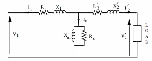
![]()
- Parameters : R1 = Primary winding resistance, R2 = Secondary winding resistance, X1 = Primary winding reactance, X2 = Secondary winding reactance, I0 = No load or exciting current, Ic= Core loss component of exciting current, Im = magnetising component of exciting current, Rc = Core loss equivalent resistance, Xm = Magnetising reactance, V1 = Primary voltage source, and V2 = Secondary terminal voltage.
Equivalent Circuit Referred to Primary Side:When all parameters are referred to primary side.
Here,


- R'2 is Secondary resistance referred to primary side
- X'2 is Secondary leakage reactance referred to primary side
- I'2 is Secondary current referred to primary side
- V'2 is Secondary voltage referred to primary side

- Secondary induced emf referred to primary side:

- Equivalent resistance referred t0 primary side:

- Equivalent reactance referred to primary side:

- Equivalent impedance referred to primary side:

Equivalent Circuit Referred to Secondary Side:When all parameters refereed to secondary side.

- Primary resistance referred to secondary side:

- Primary leakage reactance referred to secondary side:

- Primary induced emf referred to secondary side:

- Primary current referred to secondary side:

- Equivalent resistance referred to secondary side:

- Equivalent reactance referred to secondary side:

Voltage Regulation: Voltage regulation is defined as the raise in secondary terminal voltage expressed as a fraction of full load rate voltage when full load is removed while maintains input (primary) voltage constant.
Voltage regulation:

it is same as

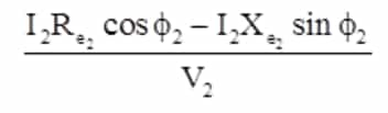
- Voltage regulation (at tagging power factor):

- Voltage regulation (at leading power factor):
Losses in Transformer
- Iron or Core Loss (Constant): The losses which occur in a transformer are as follows:
- Pi = Ph + Pe Where, Pi = Iron or core loss, Ph = Hysteresis loss, and Pe = Eddy current loss.
- This loss in the sum of hysteresis (Ph) and eddy current loss (Pe). It is denoted by Pi.
- Eddy Current Loss:

where, Ke = Proportionality constant depends upon core material, f = Supply frequency, Bm = Maximum flux density in the core, and t = Thickness of laminations.
But,

![]()
Eddy current loss is proportional to the square of the applied voltage and independent of frequency. It can be reduced by thin lamination.
- Hysteresis Loss
![]()
and

Therefore

Where, x = Steinmetz constant (range from 1.6 to 2.5). Hysteresis loss depends upon both the applied voltage and frequency.
- Copper Loss or I2R Loss (Variable):
- Total copper loss in transformer = primary winding copper loss + secondary winding copper loss.
![]()
Transformer Efficiency
- Transformer Efficiency (η ) = Output power / Input power
- Transformer Efficiency (η ) = Output power / (Output power + Losses)
- Transformer Efficiency (η ) = output power / (output power+ iron losses + copper losses)

Where, Pi = Iron or core loss, Pc = Copper loss
Transformer Tests
Open circuit and short circuit test are performed to determine the circuit constants efficiency and regulation without actually loading the transformer.
- Open Circuit (OC) Test:
- OC test is carried out at rated voltage usually on low voltage side with high voltage side open.
- This test is used to determine the core loss at rated voltage condition.
- Since, the secondary terminals are open (no load is connected across the secondary), current drawn from the source is called as no load current.
- Under no-load condition the power input to the transformer is equal to the sum of losses in the primary winding resistance and core loss.
- Since, no load current is very small, the loss in winding resistance is neglected. Hence, on no load the power drawn from the source is dissipated as heat in the core.

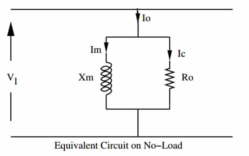
- Wattmeter reading = iron or core loss Pi
- Voltmeter reading = primary rated voltage x (V1)
- Ammeter reading = no load current (I0)
![]()

![]()


- Short Circuit Test:
- Suppose the input voltage is reduced to a small fraction of rated value and secondary terminals are short-circuited. A current will circulate in the secondary winding.
- Since a small fraction of rated voltage is applied to the primary winding, the flux in the core and hence the core loss is very small. Hence, the power input on short circuit is dissipated as heat in the winding
- Short test is carried out at rated current to determine the full load copper loss.

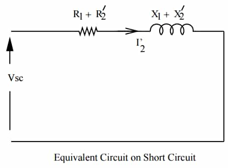
- Wattmeter reading = full load copper loss of transformer (Pcfi)
- Voltmeter reading = short circuit voltage (I1SC)
- Ammeter reading = full load primary current f(I1SC)
![]()
- Equivalent resistance:

![]() and
and ![]()
You can avail of BYJU’S Exam Prep Online classroom program for all AE & JE Exams:
BYJU’S Exam Prep Online Classroom Program for AE & JE Exams (12+ Structured LIVE Courses)
You can avail of BYJU’S Exam Prep Test series specially designed for all AE & JE Exams:
BYJU’S Exam Prep Test Series AE & JE Get Unlimited Access to all (160+ Mock Tests)
Thanks
Team BYJU’S Exam Prep
Download BYJU’S Exam Prep APP, for the best Exam Preparation, Free Mock tests, Live Classes.


Comments
write a comment