Ohm's Law : The current flowing through the electric circuit is directly proportional to the potential difference across the circuit and inversely proportional to the resistance of the circuit, provided the temperature remains constant.

The ratio of potential difference (V) between any two points of a conductor to the current (i) flowing between them is constant, provided that the temperature of the conductor remains constant.

Note: Ohm's law can be applied either to the entire circuit or to the part of a circuit
Ohm’s Law can be extended to cover inductances and capacitors as well under alternating current conditions and transient conditions. This may be stated as: V = Z I, where Z is known as the impedance function of the circuit.
- For a resistor, Z = R
- For an inductor Z = L
- For a capacitor, Z =1/ C
Example: An emf source of 6.0V is connected to a purely resistive lamp and a current of 2.0 amperes flows. All the wires are resistance-free. What is the resistance of the lamp?
Solution:
V = I R; R=V/I; R = 3.0 Ohms
Limitations of Ohm's Law: It is not applicable to the non-linear devices such as diodes, zener diodes, voltage regulators etc.
- It does not hold good for non-metallic conductors such as silicon carbide. The law for such conductors is given by

where K, m are constants.
Kirchhoff's Current Law (KCL):
- The current going into a junction or node is equal to the current going out of a node.
OR
- The algebraic sum of all the currents meeting at a junction point is always zero.

![]()
Note: Current flowing towards a junction point are assumed to be positive while current flowing away from a junction point assumed to be negative.
i1 + i2 – i3 – i4 = 0
![]()
Kirchhoff's Voltage Law (KVL): The sum of the voltages around any closed loop is equal to zero. Also, the voltage between any two nodes is the same no matter which path is taken.
![]()
Solving Problems Using Kirchhoff's Laws
To solve for the currents and voltages in a circuit, simply write all KCL and KVL equations and constitutive laws for each element and solve simultaneously. Note that some KCL and KVL equations are redundant and can be eliminated.- Write all KCL equations for each node
- Write all KVL equations for each loop
- Write all constitutive equations
- Solve simultaneous equations
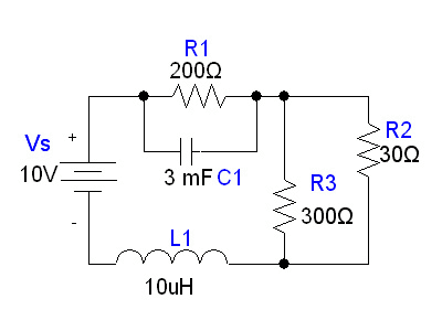 Solution: At steady state, the capacitor becomes charged and acts like an open circuit, and the inductor acts like a short circuit. Therefore, at steady state, our system is equivalent to:
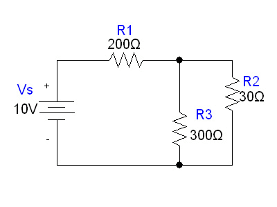
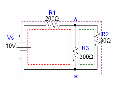
Notice in this circuit, we have two nodes (one at the top and one at the bottom) and three loops (the loop on the left consisting of Vs,R1, and R3; the loop on the right consisting of R2 and R3; and the loop around the entire perimeter, consisting of V2,R1, and R2.
Current arrows at the nodes as follows:
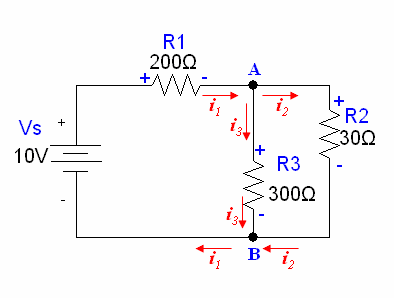 The directions for the currents were chosen arbitrarily. Keep in mind that there is no "wrong" direction when choosing the direction of the arrow, as long as we are consistent with each current's direction.
i1 = i2 + i3
10 − 200i1 − 300i3 = 0
300i3 − 30i2 = 0
Solving the system reveals the currents through each resistor:i1 = 0.044A,i2 = 0.040A, and i3 = 0.004A
We then find the voltages across each resistor using the constitutive law for resistors (Ohm's law): V = IR.V1 = (0.044)(200) = 8.8V
V2 = (0.040)(30) = 1.2V
V3 = (0.004)(300) = 1.2V
Example-2: Find the voltage and current of each element in the system.
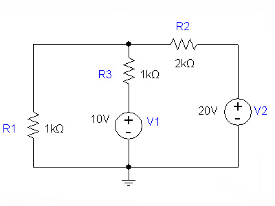
Solution: Assigning currents to the nodes:
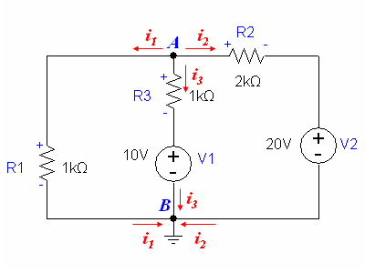
KCL equations:
Node A: − i1 − i2 − i3 = 0
Node B: i1 + i2 + i3 = 0
Again, these equations are equivalent, so we only need one of them.
KVL equations:
Left-side loop: 1000 i1 − 1000 i3 − 10 = 0
Right-side loop: 10 + 1000 i3 − 2000 i2 − 20 = 0
The constitutive law for the resistor is V = iR.
Solving the loop and node equations yields:
i1 = 0.008A, i2 = − 0.006A, and i3 = − 0.002A Using V=iR,
we can find the voltages across each resistor.
VR1 = 8V, VR2 = − 12V , and VR3 = − 2V
The negative value simply means that the voltage is actually higher on at the (-) terminal drawn in the diagram we used to derive our equations.
The voltage across the voltage source is constant, so: VV1 = 10V , and VV2 = 20V


Comments
write a comment