Time Left - 25:00 mins
National Champion Test EC: Analog Circuits
Attempt now to get your rank among 802 students!
Question 1
Consider the circuit shown in the figure. In this circuit R = 1 kΩ and C = 1 μF. The input voltage is sinusoidal with a frequency of 50 Hz, represented as a phasor with magnitude Vi and phase angle 0 radian as shown in the figure. The output voltage is represented as a phasor with magnitude V0 and phase angle δ radian. What is the value of the output phase angle δ (in radian) relative to the phase angle of the input voltage?

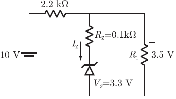
Question 2
The current through the Zener diode in figure is
Question 3
Which statement is not correct in terms of negative feedback amplifier?

Question 4
In a positive feedback Schmitt Trigger circuit, which formula is required in order to find threshold voltage?

Question 5
What is the Maximum Power Efficiency in Class B amplifier circuit
Question 6
The switch S in the circuit of the figure is initially closed. It is opened at time t = 0. You many neglect the Zener diode forward voltage drops. What is the behavior of  for t > 0?

Question 7
A voltage signal 10 sin wt is applied to the circuit with ideal diodes, as shown in Fig.Q63. The maximum, and minimum values of the output waveform Vout of the circuit are respectively

Question 8
Assuming the operational amplifier to be ideal, the gain Vout/Vin for the circuit shown in Figure is

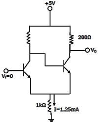
Question 9
In the schmitt trigger circuit shown in figure, If VCE(sat) = 0.1V, the output logic low level (VOL) is
Question 10
In the active filter circuit shown in figure, if Q = 1, a pair of poles will be realized with ω0 equal to

- 802 attempts
- 11 upvotes
- 9 comments
Jun 18ESE & GATE EC

