Time Left - 15:00 mins
GATE 2024 Digital Circuits Rank Booster Quiz 24
Attempt now to get your rank among 33 students!
Question 1
Consider the given circuit,
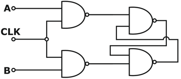
In this circuit, the race around
In this circuit, the race around
Question 2
A 3 bit module-8 ripple counter uses JK flip-flop. If the propagation delay of each FF is 40ns, the maximum clock frequency that can be used is equal to
Question 3
For each of the positive edge-triggered J-K flip flop used in the following figure, the propagation delay is ΔT
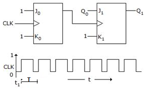
Which of the following waveforms correctly represents the output at Q1?
Which of the following waveforms correctly represents the output at Q1?
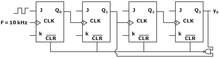
Question 4
In the following figure, the J and K inputs of all the four Flip-Flops are made high. The frequency of the signal at output Y0 is
Question 5
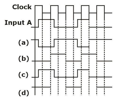
The input A and clock applied to the D flip-flop are shown in figure below. The output Q is

Question 6
consider the circuit below with initial state Q0 = 1, Q1 = Q2 = 0. The state of the circuit is given by the value of 4Q2 + 2Q1 + Q0

which one of the following is the correct state sequence of the circuit?
which one of the following is the correct state sequence of the circuit?
Question 7
A 5-bit module – 8 ripple counter uses JK flip flop. If propagation delay of each flip flop is 75 ns, find maximum clock frequency that can be used (approx.)
- 33 attempts
- 0 upvotes
- 0 comments
Dec 7ESE & GATE EC

