Time Left - 15:00 mins
GATE 2019: Digital Circuits Quiz 6 (App update required to attempt this test)
Attempt now to get your rank among 541 students!
Question 1
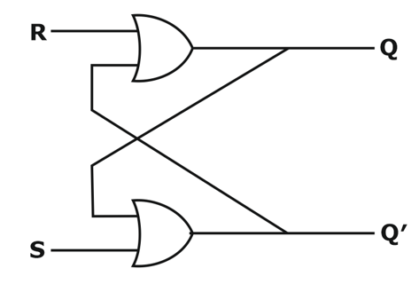
For the SR flip flop shown in figure below, what will be output Q'n+1
if (i) S = 0, R = 0
(ii) S = 1, R = 1
if (i) S = 0, R = 0
(ii) S = 1, R = 1
Question 2
The three-stage Johnson counter as shown in fig. is clocked at a constant frequency of  from the starting state of
  .The frequency of output
  will be

Question 3
Consider the circuit given below 
The clock applied to the circuit is a square wave of frequency 5 MHz and duty cycle 50%. The duty cycle for output Y is_______%
Question 4
The number of states in a 5 bit ring, 5 bit Johnson counter and the number of unused states in a 5 bit ring, Johnson counter
Question 5
Consider the logical circuit given below

Initially the counter contain ‘010’ then after 9 clock pulses which of the following is true
Initially the counter contain ‘010’ then after 9 clock pulses which of the following is true
Question 6
Assume that all the digital gates in the circuit shown in the figure are ideal, the resistor R= 10kΩ and the supply voltage is 5V. The D flip-flops D1, D2, D3, D4 and D5, are initialized with logic values 0,1,0,1 and 0, respectively. The clock has a 30% duty cycle.

The average power dissipated (in mW) in the resistor R is_____
The average power dissipated (in mW) in the resistor R is_____
- 541 attempts
- 3 upvotes
- 2 comments
Jul 14ESE & GATE EC

