Time Left - 12:00 mins
Analog Circuits: Nuclear Quiz 1
Attempt now to get your rank among 264 students!
Question 1
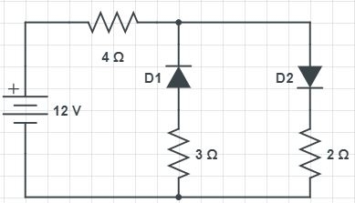
Two diodes are oppositely connected in a circuit as shown. What will be the value of the current flowing through the 12 V battery in the circuit? THE cut-in voltage of diodes are 0.7 V
Question 2
A full wave rectifier with a center tapped transformer supplies dc current of 100 mA to a load resistance of 20Ω. The secondary resistance of transformer is 1Ω. Each diode has a forward resistance of 0.5Ω. What are r.m.s. value of signal voltage across each half of the secondary as well as dc power supplied to the load?
Question 3
In the voltage regulator circuit in figure the maximum load current IL that can be drawn is 
Question 4
A silicon diode D1 as shown has voltage drop of 0.7 V under forward bias. A Zener diode D2 has breakdown voltage of 6.8 V. Select the correct option showing current through 450 Ω resistor?
Question 5
Consider the circuit shown in figure (a), the signal applied as input to the circuit is Vin [shown in figure (b)] 

The voltage across diode VD is given as (Assuming diode to be ideal)
Question 6
The input voltage Vin varies linearly from 0 to 150V.

The transfer characteristic for the figure shown below is?
The transfer characteristic for the figure shown below is?
Question 7
The capacitance of a full wave rectifier, with 60Hz input signal, peak output voltage Vp = 10V, load resistance R = 10kΩ and input ripple voltage Vr = 0.2V, is
Question 8
The diodes in the circuit shown below have linear parameters of Vγ = 0.7 (for Si) and Vγ = 0.3 (for Ge) along with rf = 0 for both types of the diodes. What is the biasing condition of diode D1, D2 and D3?

Question 9
In a half-wave rectifier, if an a.c supply is 60 Hz. Then what is the a.c ripple at output?
Question 10
calculate the regulated voltages Vo1, Vo2 and source current Is in the network shown.

- 264 attempts
- 1 upvote
- 5 comments
Jul 25ESE & GATE EC

