Time Left - 25:00 mins
GATE EE 2018 Exam: Analog Circuits Quiz 1
Attempt now to get your rank among 880 students!
Question 1
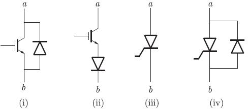
The figure shows four electronic switches (i), (ii), (iii) and (iv). Which of the switches can block voltages of either polarity (applied between terminals 'a' and 'b') when the active device is in the OFF state?
Question 2
Assuming that the diodes in the given circuit are ideal, the voltage V0 is

Question 3
The i-v characteristics of the diode in the circuit given below is,

The current in the circuit is,

The current in the circuit is,
Question 4
In the figure shown below,

the output waveform of the circuit can be represented as
the output waveform of the circuit can be represented as
Question 5
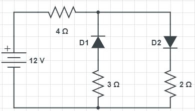
Two diodes are oppositely connected in a circuit as shown. What will be the value of the current flowing through the 12 V battery in the circuit? THE cut-in voltage of diodes are 0.7 V
Question 6
The block diagrams of two types of half wave rectifiers are shown in the figure. The transfer characteristics of the rectifiers are also shown within the block. 
It is desired to make full wave rectifier using above two half-wave rectifiers. The resultant circuit will be
Question 7
A voltage 1000 sin cot Volts is applied across YZ. Assuming ideal diodes, the voltage measured across WX in Volts is

Question 8
The equivalent circuits of a diode, during forward biased and reverse biased conditions, are shown in the figure.


If such a diode is used in clipper circuit of figure given above, the output voltage (v0) of the circuit will be
If such a diode is used in clipper circuit of figure given above, the output voltage (v0) of the circuit will be
Question 9
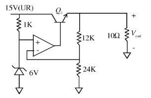
A regulated power supply, shown in figure below has an unregulated input (UR) of 15 Volts and generates a regulated output Vout. Use the component values shown in the figure.
In the figure above, the ground has been shown by the symbol.
In the figure above, the ground has been shown by the symbol.
The power dissipation across the transistor Q1 shown in the figure is:
Question 10
Diodes in the following circuit are ideal. Which is the correct waveform across RL?

- 880 attempts
- 11 upvotes
- 22 comments
Feb 23ESE & GATE EE

