Time Left - 30:00 mins
GATE EC 2021: Subject Revision Quiz 3 (App update required to attempt this test)
Attempt now to get your rank among 181 students!
Question 1
The root locus of a unity feedback control system is shown below

The open loop transfer function of the system is
The open loop transfer function of the system is
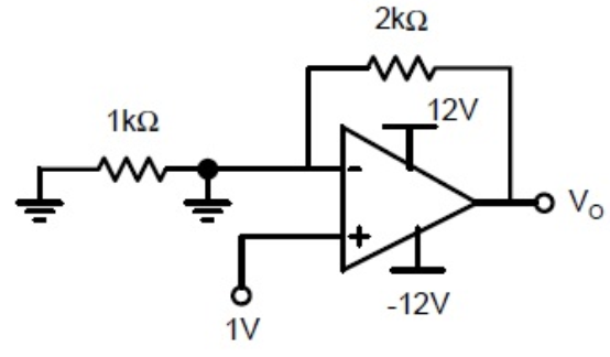
Question 2
Assuming that the opamp in the circuit shown below is ideal, the output voltage V0 (in volts) is______
Question 3
Consider the two port network given below

For the given network admittance parameter Y12 is ______ mƱ.
For the given network admittance parameter Y12 is ______ mƱ.
Question 4
The signal flow graph of a control system is given below

The number of feedback loops in the system are ___________.
The number of feedback loops in the system are ___________.
Question 5
In the transistor circuit shown below Icbo=2 A at 250 C and doubles for every 100C increase in temperature.

What is the maximum available value of Rb if the transistor is to be remain cut off at 750C?
Question 6
For the RL circuit shown in the below figure, the inductor is carrying a current of I0 for t<0.

If a unit step input is applied at t=0, then the current i(t) at t= will be (assueme
  )
)
If a unit step input is applied at t=0, then the current i(t) at t=
Question 7
For the Zener diode shown in the figure, the Zener voltage at the knee is 7V, the knee current is negligible and the Zener dynamic resistance is 10Ω. If the input voltage (Vi) range is from 10 to 16V, the output voltage (V0) ranges from

Question 8
The open loop transfer function of a unity feedback system is

The value of ‘T’ to drive the system on to the verge of instability is
The value of ‘T’ to drive the system on to the verge of instability is
Question 9
An astable multivibrator circuit using IC 555 timer is shown below. Assume that the circuit is oscillating steadily

The voltage VC across the capacitor varies between
The voltage VC across the capacitor varies between
Question 10
The forward path transfer function of a unity feedback system is

The system has 10% overshoot and velocity error constant Kv = 100.
The value of K is
The system has 10% overshoot and velocity error constant Kv = 100.
The value of K is
Question 11
A load resistance RL is to be connected between a, b such that power transferred to the load RL is maximum. The value of RL is ________Ω.

Question 12
Consider a region of silicon device of electrons and holes, with an ionized donor density of . The electric field at x = 0 is 0 V/cm and the electric field at x = L is 50 kV/cm in the positive x direction. Assume that the electric field is zero in the y and z directions at all points.

Given q =1.6 x10⁻¹⁹ coulomb, for silicon, the value of L in nm is_____
Given q =1.6 x10⁻¹⁹ coulomb,
Question 13
An n-type silicon bar 0.1 cm long and µm3 in the cross-sectional area has a majority carrier concentration of 5 × 10²⁰/m3 and the carrier mobility is 0.13 m2/V–s at 300 K. If the charge of an electron is 1.6 × 10⁻¹⁹ coulomb, if the area of the bar is (Area = 100 * 10-12) then the resistance of the bar is
Question 14
The parameters of an n-channel MOSFET are μn = 650 cm2/V-s; tox = 200 Å; W/L = 50 and VT = 0.4 V. If the transistor is biased in saturation region, the drain current(in mA) for VGS = 2V is …………
Question 15
A shunt voltage regulator using zener diode is designed with the following parameters:
Source voltage=30V, Vz= 6 volt, Pz(max)= 2W, Load current= 0-50mA, Iz(min)= 4mA
Determine the value of Rmax and Rmin required for the circuit to function properly.
Source voltage=30V, Vz= 6 volt, Pz(max)= 2W, Load current= 0-50mA, Iz(min)= 4mA
Determine the value of Rmax and Rmin required for the circuit to function properly.
- 181 attempts
- 2 upvotes
- 0 comments
Tags :
ESE & GATE ECGeneralSep 4ESE & GATE EC

