Time Left - 25:00 mins
GATE 2020: Revision Quiz 1
Attempt now to get your rank among 267 students!
Question 1
In the given circuit, the parameter k is positive and the power dissipated in the 2 Ω resistor is 12.5 W. The value of k is ________

Question 2
The total power dissipated in the circuit, shows in the figure, is 1kW. 
The voltmeter, across the load, reads 200 V. The value of XL is _________.
Question 3
For the RLC parallel resonant circuit when R = 8K Ω L = 80 mH and C = 0.50 μF; the quality factor is?
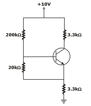
Question 4
In the circuit shown, the PNP transistor has  and
and  Assume that
  For
For  to be 5 V, the value of
  is ___________ .

Question 5
In the following circuit, what is the impedance Rb seen through base of the transistor?

Question 6
The switch SW shown in the circuit is kept at position ‘1’ for a long duration. At  the switch is moved to position ‘2’ Assuming
  the voltage
  across capacitor is

Question 7
The Z-parameters of a two-port network are:

When converted in terms of the T-parameters, the parameters were obtained as,

Determine the value of variables in Z-parameter matrix.
When converted in terms of the T-parameters, the parameters were obtained as,
Determine the value of variables in Z-parameter matrix.
Question 8
For the network of figure determine the input impedance Zi (in kΩ )Assume Vcc=22V

RS = 10 kΩ, R1 = 56 kΩ, R2 = 8.2 kΩ
CE = 20 μF, RE = 1.5 kΩ
RC = 6.8 kΩ, CC = 10 μF
RS = 10 kΩ, R1 = 56 kΩ, R2 = 8.2 kΩ
CE = 20 μF, RE = 1.5 kΩ
RC = 6.8 kΩ, CC = 10 μF
Question 9
Two AC sources feed a common variable resistive load as shown in figure below
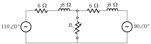
The maximum power that can be transferred to a variable load RL is _______ W.
The maximum power that can be transferred to a variable load RL is _______ W.
Question 10
For the circuit shown in figure below. Find the collector voltage ‘VC’. [Assume the β of the transistor to be infinitely high and VBE = 0.7 volts]
Question 11
The R-L-C series circuit shown is supplied from a variable frequency voltage source. The admittance-locus of the R-L-C network at terminals AB for increasing frequency  is
is

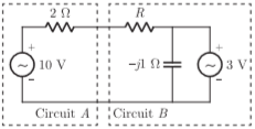
Question 12
Assuming both the voltage sources are in phase, the value of R for which maximum power is transferred from circuit A to circuit B is
Question 13
From the circuit given below, find the operating region of the transistors T1 and T2
(VTH=-0.4)

(VTH=-0.4)
Question 14
Each diode is described by a linearized volt-ampere characteristic, with incremental resistance ‘r’ and offset voltage ‘Vβ’. Diode D1 is germanium with Vβ=0 .2 V and r= 20Ω whereas Diode D2 is silicon with Vβ=0 .6 V and r= 15 Ω. Find the diode current if R=10 KΩ

Question 15
The Y-parameters of two two-port networks  and
and  are obtained as:


Determine the Y-parameters of the two port network formed by the series connection of the networks and
and  .
.
Determine the Y-parameters of the two port network formed by the series connection of the networks
- 267 attempts
- 4 upvotes
- 2 comments
Tags :
ESE & GATE EEGeneralDec 18ESE & GATE EE

