If the transistor in the circuit is made up of silicon, then the region of operation of the transistor will be
Question 2
In the circuit shown, zener diode has breakdown voltage equal to 3.3 volt while internal resistance of 0 Ω. The current through zener diode will be
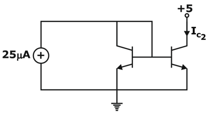
Question 3
The two transistors in circuit shown below are identical. If β = 25, then the value of current will be
Question 4
Choose the correct option. ______ Flip Flop/Latches does not have a clock input.
1) D flip flop
2) RS Latch
Question 5
Which of the following techniques can avoid race around condition in J-K flip flops?
Question 6
The compliment of the function
Question 7
The stability factor ‘S’ in BJT.
Question 8
In a J-K flip-flop, if then it acts as a/an:
Question 9
Which of the following statement are correct.
When introducing the ac model for BJT
(1) All of source are set to zero and replaced by a short circuited connection to ground for voltage sources,replaced by a open circuited connection to ground for current sources.
(2) All capacitor are replaced to be short-circuit equivalent
(3) All elements in parallel with an introduced short circuit equivalent should be removed from the network
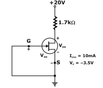
Question 10
The voltage VDS in the circuit shown below is
Question 11
Identify the combinational logic circuit(s) from the following list:
I. Full adder
II. J-K flip-flop
III. Counter
Question 12
Consider the following statements:
1) A current mirror can be used as active load because it has low output AC resistance.
2) The gain of practical op-amp at high frequencies is less as compared to that of at medium frequencies.
3) In self bias circuit for CE amplifier, the base voltage is equal to supply voltage.
Which of the above statements are incorrect?
Question 13
Consider the Boolean expression as , its simplified form is
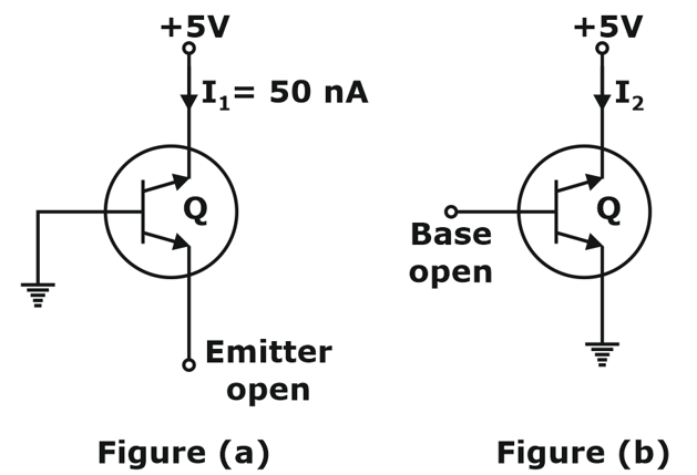
Question 14
Consider the circuits shown below.
If the transistor in both the circuits are identical with β of 49 and the current I1 of the circuit shown in figure (a) is 50 nA, then the current I2 of the circuit shown in figure (b) will be.
Question 15
(55)10 = (x)2, then x is:
Question 16
The output of circuit shown in figure Q+ is:
Question 17
Consider a transistor circuit given in figure Q point of the transistor is (10V, 2mA) Assume VBE = 0.7 V
Value of R1 for the circuit is
Question 18
Which of the following logic gate generates a HIGH output when an odd number of input are HIGH.
Question 19
To generate 2 MHz frequency, the most suitable circuit is
Question 20
Assertion (A) - The small signal analysis of a transistor amplifier is done to obtain the current gain, voltage gain and the conversion efficiency of an amplifier. Reason (R) – The small signal analysis of a transistor amplifier uses the small signal parameters of the transistor.