XOR Gate – Definition, Symbol, Diagram
By BYJU'S Exam Prep
Updated on: September 25th, 2023

The XOR gate or Exclusive-OR gate is achieved by combining standard logic gates. XOR gate is used extensively in error detection circuits, arithmetic logic circuits, and computational logic comparators.
The Exclusive OR gate gives the output only if its two inputs are not similar, namely if one of them is one (high) and the other is zero (low). In this article, we will learn about the Exclusive-OR Gate (XOR), its logical symbol, truth table, circuit diagram, applications and various properties.
Download Formulas for GATE Computer Science Engineering – Programming & Data Structures
Table of content
What is the XOR Gate?
An XOR gate is a two-input single-output logic gate whose output is assumed to be HIGH(one) only when one of its inputs is HIGH(one).
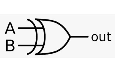
XOR Gate Symbol
The logic symbol for a two-input XOR gate is shown below:
XOR Gate Expression
If input variables are represented by A and B, then the logical expression for output is
_ _
Y = AB + AB = A ⊕ B
Download Formulas for GATE Computer Science Engineering – Discrete Mathematics
What is the Truth Table of XOR Gate?
Practically three or more input XOR gate does not exist. But when more than two variables are XOR, a number of two input XOR gates are cascaded where the output is assumed to be ‘1’ when the odd number of input variables is ‘1’.
The XOR gate is also known as the odd number of 1’s detector in the input.
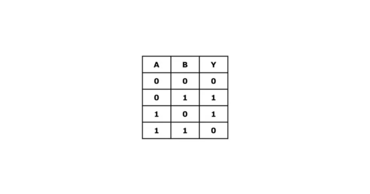
Figure: XOR Gate Truth Table
Download Formulas for GATE Computer Science Engineering – Algorithms
Application of XOR Gate
The most important application of the XOR gate is in parity generation and detection. Hence, it is also known as the staircase switch. The switching circuit of the XOR gate is shown.
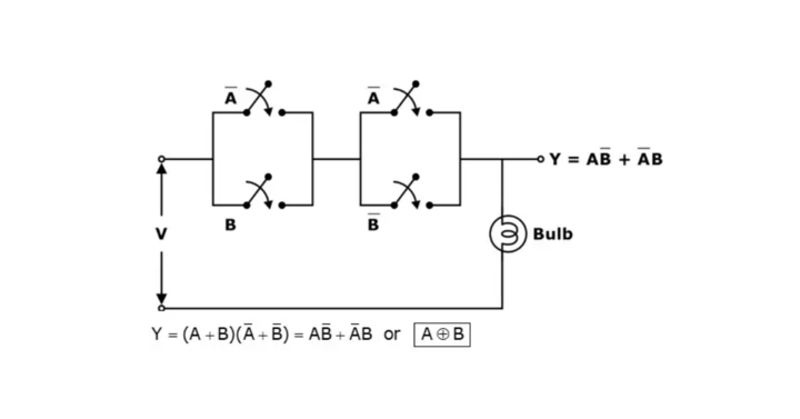
The Exclusive OR gate follows both commutative and associative law.
Enable and Disable Inputs
For an XOR Gate 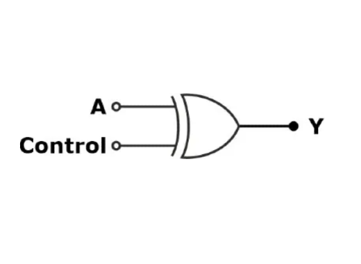
For control = 0;
|
A |
Control |
Y |
|
0 |
0 |
0 |
|
1 |
0 |
1 |
Thus, the EX-OR gate acts as a buffer for controlled input of logic ‘0’.
For control = 1;
|
A |
Control |
Y |
|
0 |
1 |
1 |
|
1 |
1 |
0 |
Thus, the XOR gate acts as an inverter for logic ‘1’ control input.
Properties of XOR Gate
A ⊕ A = 0
A ⊕ 0 = A
A ⊕ A̅ = 1
A ⊕ 1 = A̅
A ⊕ A ⊕ A = A
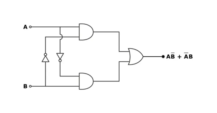
The internal diagram of the EXOR or XOR gate is as follows: