
- Home/
- GATE ELECTRONICS/
- GATE EC/
- Article
Thevenin’s Theorem
By BYJU'S Exam Prep
Updated on: September 25th, 2023

The theorem we use for solving the given electrical network/circuit is known as Network Theorem / Circuit theorem. Thevenin’s Theorem is a fundamental Network theorem. Thevenin’s theorem is useful for representing the given electric circuit into its equivalent circuit in the simplified form.
This article overviews Thevenin’s theorem and how to represent Thevenin’s equivalent circuit for the given circuit. Here, first, you will get to know Thevenin’s theorem and then the procedure of this method.
Download Formulas for GATE Electronics & Communication Engineering – Control System
Table of content
What is Thevenin’s Theorem?
According to this Theorem, every circuit that contains a voltage source and resistors may be reduced to just a single voltage source and resistor.
Thevenin’s Theorem Statement
Thevenin’s theorem states that any 2-terminal linear and bilateral network or circuit having multiple independent and dependent sources can be represented in a simplified equivalent circuit known as Thevenin’s equivalent circuit.
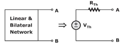
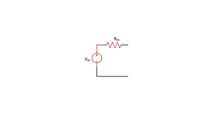
Thevenin’s equivalent circuit consists of a Thevenin’s voltage source, VTh, in series with Thevenin’s resistance, RTh. Therefore, the series combination of voltage source and resistor is a practical voltage source. Hence, we can say that Thevenin’s equivalent circuit is nothing but a practical voltage source.
Download Formulas for GATE Electronics & Communication Engineering – Digital Circuits
Thevenin’s Theorem Steps
It will take more time than the normal methods to find the response of an element if the network/circuit has multiple sources and resistances. However, we can use Thevenin’s theorem at that time to find the response easily. Now, let’s see the steps for finding the response of an element when multiple sources and resistances are present in the network/circuit by using Thevenin’s theorem.
- Step 1: Remove the element where we are supposed to find the response from the given circuit. After the removal of the element, the terminals will be open.
- Step 2: Find the voltage across the open-circuited terminals of the circuit obtained in Step 1. This voltage is known as open-circuit voltage, Thevenin’s equivalent voltage, or Thevenin’s voltage, VTh.
- Step 3: Replace all the independent sources with their internal resistances in the circuit obtained in Step 1.
- Step 4: Find the equivalent resistance across the open-circuited terminals of the circuit obtained in Step 3 indirect methods if there are no dependent sources. This equivalent resistance is known as Thevenin’s equivalent or Thevenin’s resistance, RTh in short.
- Step 5: If dependent sources are present, then we can find the equivalent resistance across the open-circuited terminals of the circuit obtained in Step 3 by using the test source method. We will connect a 1V source (or 1A source) across the open terminals and calculate another parameter current (or voltage) in the test source method. We will get the value of Thevenin’s resistance, RTh, by taking the ratio of voltage and current across the 2 terminals.
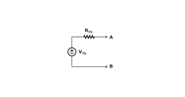
- Step 6: Draw Thevenin’s equivalent circuit by connecting Thevenin’s voltage, VTh, in series with Thevenin’s resistance, RTh.
- Step 7: Connect the element, where we are supposed to find the response at the open terminals of Thevenin’s equivalent circuit obtained in Step 6.
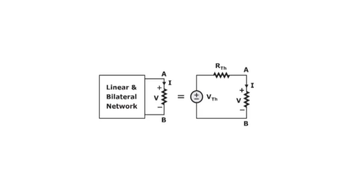
- Step 8: Find the response of that element by using basic laws or rules. Here, I= (Vth/RTh+R) & V= VTh (R /RTh+R).
Download Formulas for GATE Electronics & Communication Engineering – Electronic Devices
Norton’s Equivalent of Thevenin’s Theorem
Norton’s and Thevenin’s circuits are interchangeable by an equivalent circuit; this is used as per convenience in complex electrical networks. Consider we have the following general circuit:
Thevenin Equivalent of the Network:
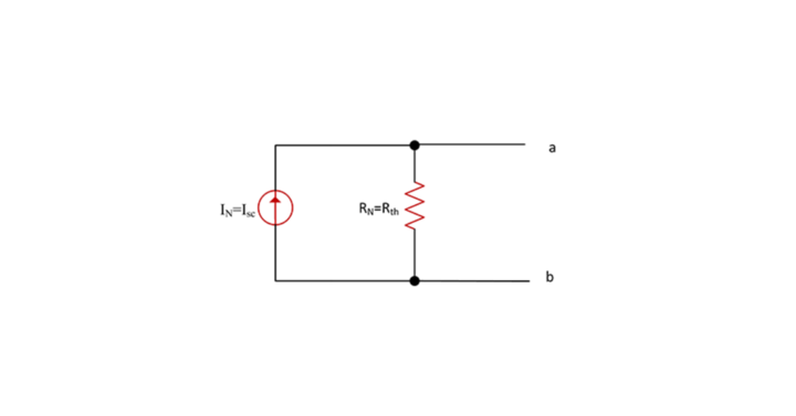
Norton Equivalent of the Network:
Both of these circuits can be interchanged in a network by the following relation:
Rth = RN
IN= Vth / Rth
Rth= Vth / IN
Vth = IN. Rth
The equivalent Norton circuit is:
Thevenin’s Theorem Problems
Question 1: Thevenin’s theorem finds the voltage V of the following electric circuit.
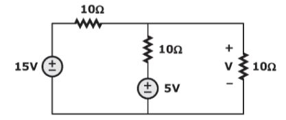
Answer: 20/3 volts
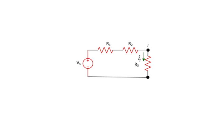
Question 2: Find the current ‘I’ of the following electric circuit by using Thevenin’s theorem.
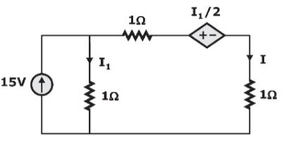
Answer: 1 A
Limitation of Thevenin’s Theorem
Thevenin’s theorem is handy for simplifying complex linear networks, but despite its usefulness, it has a few limitations. Certain conditions need to be taken care of before applying the theorem. The conditions are as follows:
- As many circuits have linear characteristics only within a certain range of values, the Thevenin equivalent is valid only within these ranges.
- In Thevenin’s equivalent, the I-V characteristics are equivalent only from the load’s point of view.


