
- Home/
- GATE ELECTRONICS/
- GATE EC/
- Article
Tellegen’s Theorem
By BYJU'S Exam Prep
Updated on: September 25th, 2023

Bernard D.H. Tellegen, a Dutch electrical engineer and inventor published Tellegen’s Theorem in 1952. Tellegen’s theorem is the most fundamental network analysis theorem from which most other theorems are derived. Having an understanding of this fundamental theorem will help us to understand how physical impedance functions function.
Tellegen’s theorem can be applied to lump systems that consist of linear, active, passive, and time-varying elements. Likewise, this theorem is convenient for networks following Kirchhoff’s voltage and Kirchhoff’s current law.
Download Formulas for GATE Electronics & Communication Engineering – Digital Circuits
Table of content
What is Tellegen’s Theorem?
The theorem is based on the conservation of power and energy in an electric circuit. Tellegen’s theorem applies to any network that follows basic Kirchoff’s current and voltage laws;
Tellegen’s Theorem Statement
The theorem states that the amount of power consumed by various elements in various branches equals zero. The theorem is based on the law of conservation of energy.
bΣb=1[vbib] = 0
Where b represents the number of branches, and vb and ib are the branches’ current and voltage values.
Applications of Tellegen’s Theorem
The applications of Tellegen’s theorem revolve around synthesizing power in electrical networks. Some practical applications of the theorem are listed below-
- The theorem is used by digital signal processing for filter design.
- This theorem determines the stability of complex systems in chemical plants and the oil industry.
- The theorem is used in reaction network topology and structure analysis.
Download Formulas for GATE Electronics & Communication Engineering – Electronic Devices
Steps Involved in Tellegen’s Theorem
Using Tellegen’s theorem can be broken down into a few simple steps. The steps are as follows.
- Step 1: The first step is to identify the number of branches in the given electrical network and then calculate the power dissipated across each branch using a conventional method.
- Step 2: We can find the instantaneous power of each branch.
- Step 3: There are two branches: power-delivering branches and power-absorbing branches. We have to identify the power-delivering branch and the power-absorbing branch.
- Step 4: It is appropriate to assume a positive voltage drop in the power-delivering branch and a negative voltage drop in the power-absorbing branch. Of course, the signs can also be reversed, but whatever the convention should be carried throughout.
- Step 5: All power calculated from all branches must be added to justify Tellegen’s theorem. This sum must always be zero.
Tellegen’s Theorem Example
Consider the figure below, with two DC supplies and a few resistors. We will find the branch’s current and potential drop or delivered values and will try to facilitate Tellegen’s theorem.
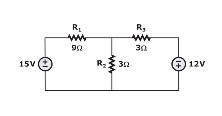
- Step 1:
Identifying the number of branches, Since there are 5 different elements in different positions, we can conclude the number of branches to be 5; So, b=1,2,…5
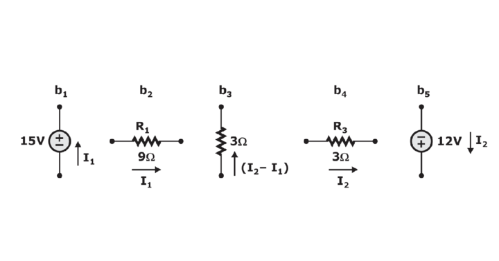
- Step 2:
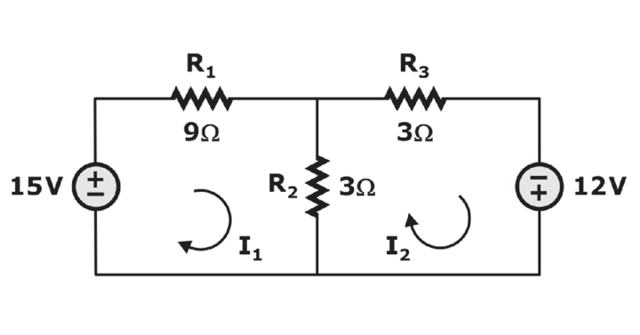
Calculating the current and voltage drop or delivered in each branch can later be used for calculating power in each branch.
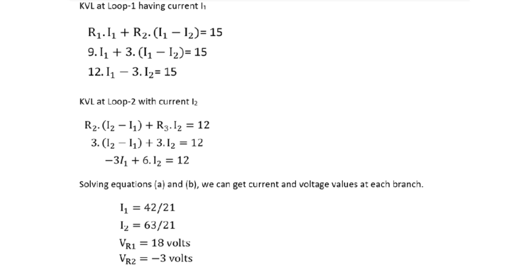
Using KVL, we will apply simple loop equations :
- Step 3: Identifying power delivering and power dissipating branches by calculating power at each branch.
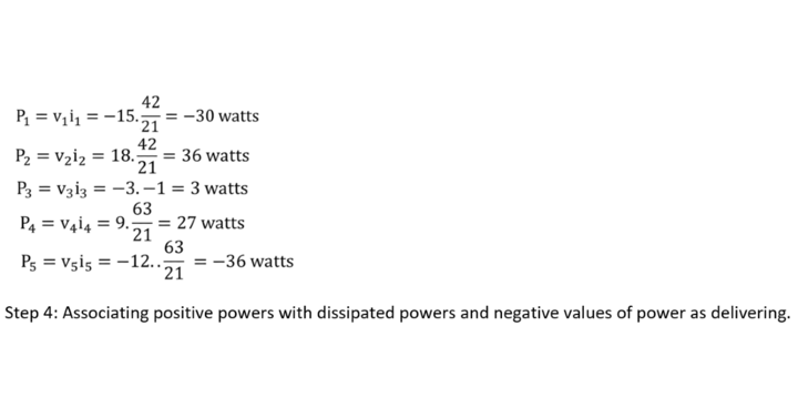
We decide that branches 1 and 5 are delivering while the rest of the branches are dissipating, which makes sense since a resistance dissipates power, and a supply delivers it.
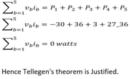
Step 5: Justify Tellegen’s theorem by taking the algebraic summation of the power values in the network. We should get zero results by the conservation of energy or power law.
Download Formulas for GATE Electronics & Communication Engineering – Control System


