
- Home/
- GATE ELECTRICAL/
- GATE EE/
- Article
Speed Control of Induction Motor
By BYJU'S Exam Prep
Updated on: September 25th, 2023

Conventionally, DC shunt motors are popular for the wide range of speed control of induction motors. However, the induction motor’s speed can vary by varying its synchronous speed and slip. For the squirrel cage induction motor, the speed can be controlled through the stator only, but for a slip ring induction motor, its speed can be controlled through the stator and its rotor.
Speed Control of Induction Motor PDF [GATE Notes]
The speed control of induction motor is maintained at the expense of efficiency loss and a low electrical power factor. Here, we will explore the speed control of the induction motor in detail and discuss various speed control methods that can be used.
Table of content
Speed Control of Induction Motor
The speed control of induction motor is done to modify the currents in an induction motor to control speed. The expression for the speed (N) of an induction motor is
N=Ns(1−s)
Hence, we can obtain control over the speed by varying its synchronous speed (Ns) or changing its slip (s). The synchronous speed of the induction motor depends on the supply frequency and the number of stator poles. The torque of an induction motor while running is given by
T=[3×60/2πNs]×sE22R2/R22+(sX2)2
Hence for a given torque and load, we can vary the rotor voltage and rotor resistance to vary the slip for the speed control of induction motor.
Speed Control Methods of Induction Motor
From the stator side, we can obtain the speed control of induction motor by using the following methods, namely.
- Voltage Control Method
- Frequency Control Method
- Pole Changing Method
- Stator Resistance Method
From the rotor side, the speed control of induction motor can be achieved by the following methods.
- Rotor Resistance Control Method
- Slip Power Recovery Method
- Cascading (or) Tandem connection
Let us briefly discuss these speed control methods of the induction motor.
Voltage Control Method
In this method of speed control of induction motor, the supply voltage is varied using an autotransformer. Practically, we cannot increase the voltage levels beyond the rated voltage as the insulation stress will increase and lead to insulation failure.
T=[3×60/2πNs]×sE22R2/R22+(sX2)2
During running, the slip is tiny; hence (sX2)2 can be neglected
⇒T 𝛼 sE22
And the E.M. F induced in the rotor (E2) is proportional to the stator voltage (V)
⇒T 𝛼 sV22
The above equation makes it evident that torque will likewise drop if the supply voltage is reduced. If the voltage reduces for a given load, the slip will increase while reducing the speed to maintain the load torque constant. Voltage can be reduced to a suitable value; the motor will become unstable if we reduce the voltage below this value. This type of speed control of induction motor is rarely employed since it results in an overheated induction motor because a minor change in speed necessitates a considerable voltage reduction.
Frequency Control Method
The flux density of the stator core is inversely proportional to the applied frequency. To reduce the core losses and for the better performance of the motor, the maximum flux density (Bm) must be maintained constant.
Bm 𝛼 V/f
So, to maintain the maximum flux density as constant, we must vary the voltage and frequency. This method cannot be possible for frequencies greater than the rated frequency as voltage also needs to be increased, which is impossible due to insulation constraints. This method requires variable voltage and variable frequency converters, which makes this method an expansive one. Still, this method offers a wide range of speed control without affecting the efficiency of the motor.
Pole Changing Speed Control
This method of speed control of induction motor can only be applied to the squirrel cage induction motor. The number of poles in the rotor of a slip ring induction motor is fixed, whereas the squirrel cage rotor can be adapted to any number of poles. The poles of the induction motor can be changed in two ways.
- Multiple winding sets
- Consequent pole changing
In the first method, we use multiple winding sets of stator windings designed for different sets of poles. While in operation, any one of them can be connected according to the speed requirements of the user, and the other sets will keep in open. We know that
Ns=120f/P
As the number of poles increases, the speed will be reduced. This method can only vary the speed in steps, and it is expansive as it involves multiple stator windings.
In the method of consequent pole changing, we can obtain another set of poles by reversing the coils. This method can only give two sets of speeds.
Stator Resistance Method
This speed control method of induction motor is similar to the voltage control method. It requires three rheostats to be connected in series with each phase of the stator winding to reduce the voltage and achieve the required speed. As there is some power loss due to the rheostats, this method will be preferred for the low-rating machines for a small duration. This method is more advantageous in starting than speed control.
Rotor Resistance Control Method
This speed control method of induction motor can be possible for the slip-ring induction motor only as we cannot access the rotor of the squirrel cage induction motor. This method connects external resistance to the rotor through the slip rings and brushes while running. Hence it leads to the reduction of the torque.
T=[3×60/2πNs]×sE22R2/R22+(sX2)2
For the given stator voltage, the E.M.F induced in the rotor E2 is constant, and during running, the slip is tiny; hence (sX2)2 can be neglected.
⇒T 𝛼 s/R2
But to maintain the load torque constant, the speed of the rotor will decrease, and the slip will increase. As the operating slip increases, this method is inefficient and unsuitable for a wide range of applications. The main benefit of this method is that starting torque increases with the addition of external resistance, but it also has significant drawbacks.
- It is not possible to travel at speed higher than usual.
- Huge speed changes necessitate big resistance values, yet adding such large values will result in significant copper loss and a drop in circuit efficiency.
- More losses result from the presence of resistance.
- The squirrel cage induction motor cannot be operated using this method.
Slip Power Recovery Method
In this method of speed control of induction motor, we inject the external voltage into the rotor through slip rings and brushes at a slip frequency (sf) To obtain steady-state torque. This could be done in two ways.
In the first method, we increase the rotor voltage, which leads to an increase in speed for a given load. We know that
T 𝛼 sE22
If the rotor voltage is increased, the torque will increase; subsequently, the rotor speed will increase, and the slip will decrease.
In the second method, we decrease the voltage in the rotor, then the torque will decrease, the speed will increase, and the slip will decrease. The Scherbius drive is the best example of this kind of operation.
Cascading or Tandem Connection
In this method of speed control of induction motor, we need two induction motors, one is essentially a slip ring induction motor, and the other is either a slip ring induction motor or a squirrel cage induction motor. Both machines will be mechanically coupled; the first motor is a slip ring induction motor which feeds the second one through its slip rings.
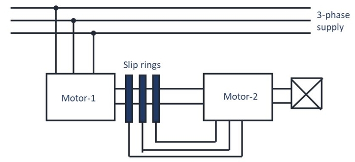
The speed of the slip-ring induction motor is
Ns1=120 f/P1
The speed of the second motor is
Ns2=120s1f/P2
In this method, four different speeds are possible. They are
- 120 f/P1+P2 in cumulative cascading
- 120 f/P1−P2 in differential cascading
- 120 f/P1 (When motor-1 only operating)
- 120 f/P2 (When motor-2 only operating)
In differential cascading, the number of poles in both motors should not be equal.


