
- Home/
- GATE ELECTRONICS/
- GATE EC/
- Article
Simple Op Amp Circuits
By BYJU'S Exam Prep
Updated on: September 25th, 2023

When we talk about simple Op amp circuits, we refer to the basic circuits constructed using operational amplifiers. These circuits are commonly used as blocks of systems and contribute to their basic functioning. We will use basic linear elements in conjunction to construct simple Op-amp circuits.
The article goes through some basic simple diode circuits and their applications according to the response. First, we will see the basics of Op amp and then build our way towards understanding these circuits.
Table of content
Op Amp Basics
Operational amplifiers are convenient building blocks that can be used to build amplifiers, filters, and in some cases, analog computers. Op ampere integrated circuits are composed of many transistors and resistors such that the resulting circuit follows a certain set of rules. The schematic of a basic Op amp is shown below.
It amplifies the voltage difference between the two inputs, and then that voltage appears at the output. The ideal Op amp has infinite gain. It amplifies the voltage difference between the two inputs, and then that voltage appears at the output.
Rules in Basic Simple Op amp Circuits
Two rules will help us in figuring out the behavior of Op amp in simple Op amp circuits-
- Input pins have infinite input impedance; hence, no current will flow into them.
- As the output adjusts itself and attempts to make sure the input is at the same voltages.
Basic Simple Op amp Circuits
We will discuss some of the basic simple Op amp circuits and briefly go through their construction and respective response. There are also some common operational circuits that we will discuss in a later section of this article.
Inverting Op Amp
This configuration feeds back the output to the negative or inverting input through a resistor (R2). Next, the input signal is applied to this inverting pin through a resistor (R1). Finally, the positive pin is connected to the ground.
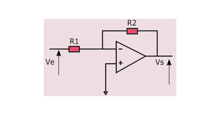
The response is given by: VS=-Ve R2/R1.
When R1 and R2 are equal, the configuration produces a complementary signal as the output is the opposite of the input.
The input offset voltage measures how much the voltage drop at the +ve input is offset by the voltage drop at the -ve input. This is because the real Op amp isn’t perfect and draws a small bias current into both inputs.
Non-inverting Op Amp
There is a lot of similarity between this device and the inverting amplifier, except that non-inverting amplifiers have input voltage applied directly to their non-inverting pin. At the same time, the feedback loop ends on the ground.
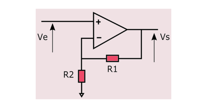
The response is given by: VS=-Ve (1+R1/R2)
These configurations allow the amplification of one signal. In addition, it’s possible to amplify several signals by using summing amplifiers. To to avoid overvoltages, the output should not exceed the power supply voltage when dealing with larger signals.
Voltage Follower
Another basic circuit that falls under the category of simple Op amp circuits is a Voltage follower or a buffer. A voltage buffer is the simplest circuit since it does not require external components. However, since the voltage output equals the voltage input, some might wonder whether this type of op-amp circuit is useful.
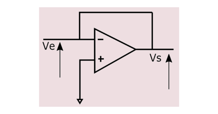
The response is given by: VS=Ve
A circuit such as this can create a very high impedance input and a very low impedance output. This can be useful for interfacing logic levels between components or powering a voltage divider power supply.
It is preferred to connect the input terminals to the ground via a high-value resistor such that the potential to the terminal remains at zero even if the input terminal is disconnected and a possibility of some potential exists due to very high input impedance.
Operational Simple Op Amp Circuits
Great, we have seen basic simple Op amp circuits, and have a slight idea about op-amps basic applications. Apart from these, there are some important operational applications as well, which are used extensively in a system. Keep reading to understand the type of block applications Op amp can serve.
Non-inverting Summing Amplifier
The non-inverting operational amplifier circuit is an operational simple Op amp circuits that can add only two voltages by adding 2 resistors on the positive pin. Using this for multiple voltages is not very flexible since it requires several resistors.
The response is given by: VS=V1 + V2
If a third voltage is added with the same resistances, the formula would be VS=⅔ (V1+V2+V3). It would then be necessary to change the resistors so that VS=V1+ V2+ V3 or use an inverting summer amplifier.
Inverting Summing Amplifier
The voltages are summed by adding parallel resistors to the inverting input pin of the inverting operational amplifier circuit.
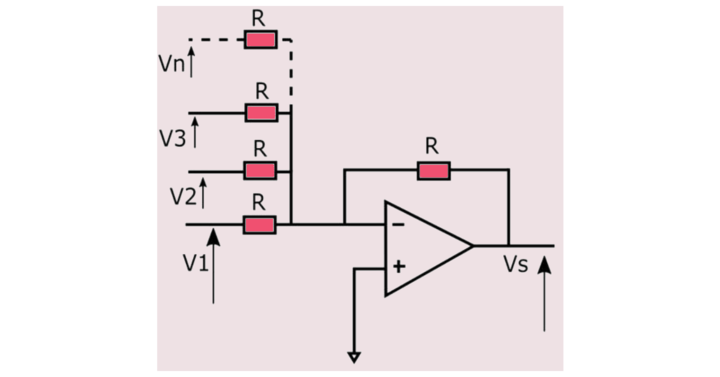
The response is given by: VS=-(V1+V2+V3+…+Vn)
In this case, it is possible to add any number of voltages without changing the value of resistors, as opposed to the non-inverting summing amplifier.
Newer Op-amp is chopper stabilized (they measure and null the input offset error at regular intervals). In addition, some newer Op amp have null pins that allow you to null the offset error.
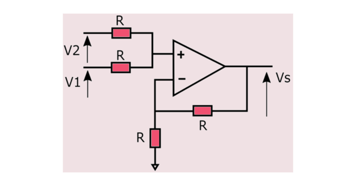
Differential Amplifier
With inverting operational amplifiers, a voltage applied to the inverting pin was amplified, resulting in an output voltage that was out of phase with the input voltage; the non-inverting pin was attached to the ground. The differential amplifier in simple Op amp circuits is one of the most common application using an operational amplifier.
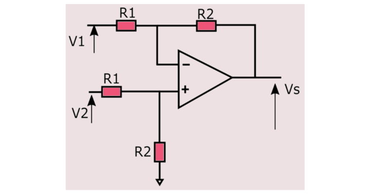
The response is given by: VS=R2/R1 (V2-V1)
We get a differential amplifier by using a voltage divider on the non-inverting side of the above configuration.
The difference amplifier lets us add or compare voltages. If the resistors used differ by some small percentage from their actual values, we can use a precision resistor. Generally, getting a manufactured unit of difference amplifier is better than creating it from circuit elements.
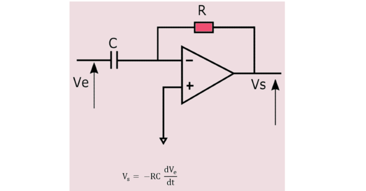
Integrator
Using a square wave generator or digital clock generator allows us to produce a square wave easily. Then, we can integrate the square wave signal for our need for triangular waves. Finally, an operational amplifier integrates the input signal using a capacitor, resistor, and capacitor on the inverting feedback path.

As a result of saturation issues, a resistor is often connected in parallel to the capacitor. As a result, the capacitor acts like a closed circuit and blocks feedback voltages if the input signal is a low-frequency sine wave. Integrator is one of the very important operational simple Op amp circuits.
Be aware that a resistor is often connected in parallel to the capacitor for saturation issues. Indeed, if the input signal is a low-frequency sine wave, the capacitor acts like an open circuit and blocks feedback voltage. The circuit behaves like an inverting amplifier with a low frequency since a resistor in parallel to the capacitor prevents saturation from occurring.
Op Amp Differentiator
By swapping the capacitor and resistor, the same circuit we used as an integrator will work as a differentiator.
Differentiator circuit is also a very common and important part of simple Op amp circuits from the operational point of view.
|
Important GATE Topics |
|
| Lan Full Form | Propped Cantilever Beam |
| Torsional Force | POP Full Form |
| RTC Full Form | Fcfs Scheduling Full Form |
| Types Of Loads | E-Commerce Mcq |
| Laser Full Form | Rankine Formula |


