
- Home/
- GATE ELECTRONICS/
- GATE EC/
- Article
Resistors in Series
By BYJU'S Exam Prep
Updated on: September 25th, 2023

The connection of resistors in series is an electrical circuit where resistors are connected in sequence. In an electric circuit, a resistor is an electrical component that can be implemented as electrical resistance. It is a passive two-terminal component which is used to minimize the current flow and reduce the voltage level of the circuit. A circuit may consist of any number of resistors depending on the amount of current or voltage required in the circuit.
To limit the current and voltage in the circuit, connection of resistors in series combination, parallel combination or sometimes both types of combination are used in a single circuit. The article elaborates on the need for a series combination and equivalent circuit resistance on connecting resistors in series, along with some examples.
Download Formulas for GATE Electronics & Communication Engineering – Control System
Table of content
Resistors in Series
Resistors are said to be in series connection when the current across all the resistors is the same, and the voltage across the individual resistor is different. Although if all the resistors in series have the same resistance, then the voltage across each resistor will also be the same.
Resistors in series are used as a resistance voltage divider circuit. Also, resistors in series distribute the heat occurring due to power dissipation among resistors, thus doesn’t load the circuit.
Need for Series Combination of Resistors
When the same current flows through the resistors and the potential developed across the resistors is different, the combination is said to be a series combination of resistors. If a fault occurs on any one of the resistors in the circuit, the entire circuit will get affected or turned off. Resistors in series can be modeled as shown below:
Resistors are connected in series for the following purposes:
- Increase the effectiveness or overall resistance.
- Divide the potential V between all the resistors to get a small value of potential.
- Resistors in series spread the heat dissipation and thus won’t load the circuit.
Download Formulas for GATE Electronics & Communication Engineering – Digital Circuits
Equivalent Resistance of Resistors in Series
For simplification, let us calculate the equivalent resistance for the two resistors connected in series as shown below:
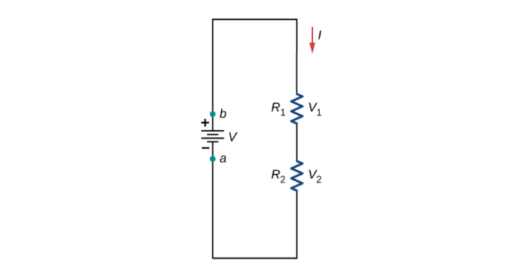
In the above circuit, the same current i flows through the resistors R1 and R2. If R1≠R2, then v1≠v2.
From Ohm’s law,
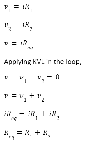
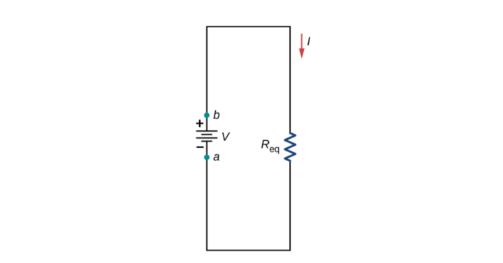
Where Req is the effective resistance of the circuit and can be modelled as:
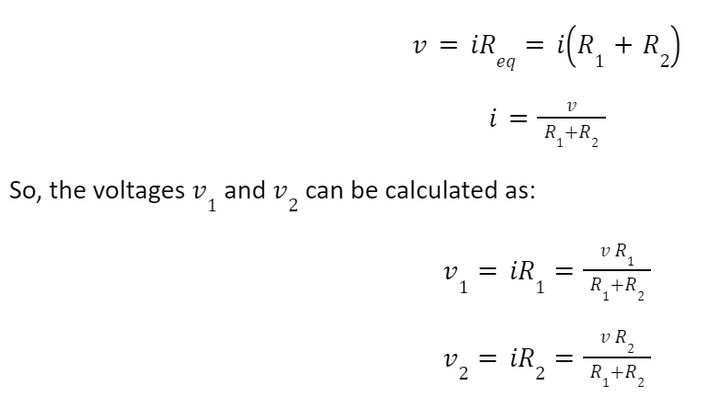
The source voltage v is divided between R1 and R2. This is known as the principle of voltage division.
Similarly, let us calculate the equivalent resistance for the three resistors connected in series as shown below:
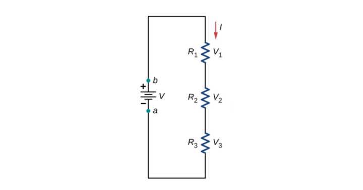
Let v1 be the voltage drop across resistor R1
Let v2 be the voltage drop across resistor R2
Let v3 be the voltage drop across resistor R3
From Ohm’s law,
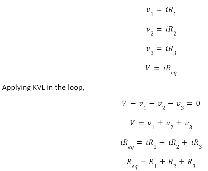
Where Req is the effective resistance of the circuit where we connected resistors in series and can be modeled as:

Download Formulas for GATE Electronics & Communication Engineering – Electronic Devices
Resistors in Series Formula
When N a number of resistors are connected in series then the overall equivalent resistance is the sum of individual resistance connected in the circuit. Mathematically, resistors in the series formula can be written as:
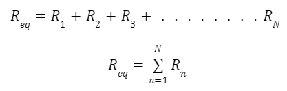
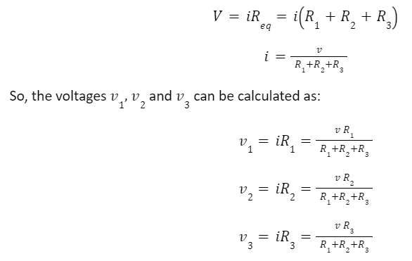
Similarly, the voltage across any resistor connected in series can be calculated as:
Vn = VRn/ Req
Resistors in Series Examples
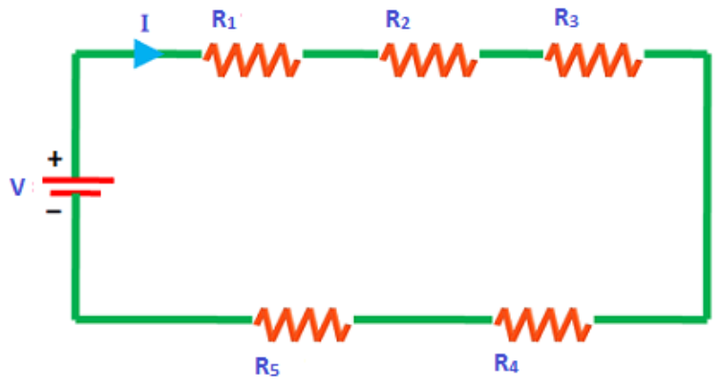
Example 1: Find the source current I from the figure shown below:
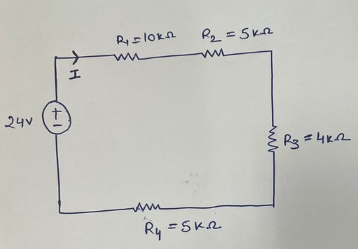
Solution: From the above circuit, the current is the same across all the resistors, so resistors are in series. The above circuit can be modeled as an equivalent resistance circuit as shown below:
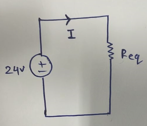
Req =R1+R2+R3+R4 = 10 + 5+4+5=24 kΩ
So, from ohm’s law,
I=V/Req =24 V/24kΩ = 1 mA
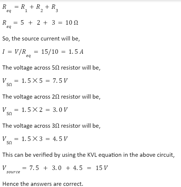
Example 2: Find the equivalent resistance seen from the terminal ab and the voltage across each resistor in the circuit shown below:
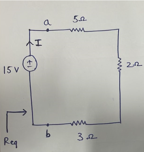
Solution: From the figure, resistors are in series so that the equivalent resistance can be calculated as,
Difference Between Resistors in Series and Parallel
In brief, the difference between resistors in series and resistors in parallel is shown below in tabular form based on certain parameters. Let Vn be the voltage across the resistors and in the current across the resistors.
|
Parameters |
Resistors in series |
Resistors in parallel |
|
Definition |
When there exists only a path of current to flow, and source voltage divides across the resistors with the same current across all resistors. |
When there exists multiple paths of current to flow and current divides across the resistors with the same voltage across all resistors. |
|
Source Voltage V |
Source voltage gets divided between all the resistors in series. V=V1+V2+V3 . . . . Vn |
Source voltage appears across each resistor in parallel. V=V1=V2=V3=… =Vn |
|
Source Current I |
Source current only flows from each resistor in series. I=I1=I2=I3=. . . =In |
Source current gets divided between all the resistors in parallel. I=I1+I2+I3 . . . . In |
|
Voltage across resistors |
Different if all resistors have different resistance. Same if all resistors have the same resistance. |
Always the same irrespective of the resistance value. |
|
Current across resistors |
Always the same irrespective of the resistance value. |
Different if all resistors have different resistance. Same if all resistors have the same resistance. |
|
Equivalent Resistance |
The equivalent resistance is greater than all the resistance present in the circuit. Req=R1+R2+R3+ . . . . . . Rn |
The equivalent resistance is always less than the smallest resistance present in the circuit. 1/Req=1/R1+1/R2+1/R3+ . . . . . . 1/Rn |
|
Important GATE Topics |
|
| Fixed End Moment | Gravity Of Earth |
| Slope Deflection Equation | Capacitors in Parallel |
| Capacitors in Series | Carnot Cycle |
| Cement Test | Clamping Circuit |
| CMOS Converter | Column Base |


