
- Home/
- GATE ELECTRONICS/
- GATE EC/
- Article
Rectifier Circuit
By BYJU'S Exam Prep
Updated on: September 25th, 2023

Rectifier circuits play a vital role in the DC power supplies for converting the AC signal into a DC signal. Based on the requirement, we will use the respective rectifier circuit. p-n junction diodes have a lot of applications. Rectifier circuits are one among them. In this article, get an overview of rectifiers and their classification.
We used to receive the electrical signal in AC form (sinusoidal form) to the houses. But we can operate many electronic devices and ICs with DC supply only. So accordingly, we will use the respective electronic circuit for converting the AC input into DC output. We can do this conversion by using the Rectifier circuit. Here, we will read about the Rectifier Circuit definition, diagram, and various types of recitiers used in Rectifier Circuit.
Table of content
Rectifier Circuit Definition
The process of converting an AC (sinusoidal) signal into a DC signal is called Rectification. The electronic circuit which performs the rectification is known as the Rectifier circuit. In short, we can call it a rectifier. So, by using this circuit, we can convert the electrical signal, which is of sinusoidal (AC) form, into DC form.
Rectifier Circuit Diagram
Here is a diagram of a commonly used rectifier circuit:
In an AC signal, the current flows in one direction for one-half cycle and the opposite direction for the other half cycle. Whereas in a DC signal, the current flows in only one direction. We know that the p-n junction diode is the unilateral element. Hence, the p-n junction diode is the main electronic component in the rectifier circuit.
Types of Rectifiers in Rectifier Circuit
In this article, we are focusing on one of the important applications of Diodes. i.e., Rectifiers. We assume all the diodes we use in the circuit diagrams are ideal. Rectifiers can be classified based on the portion(s) of the input AC signal (positive half cycle, negative half cycle) rectified at the output, placing the Diode in the circuit. Now, let us discuss the following types of Rectifiers used in the Rectifier Circuit given below:
- Half Wave Rectifier
- Full Wave Rectifier
Half Wave Rectifier in Rectifier Circuit
In a Rectifier circuit, a rectifier is said to be a half-wave rectifier if it rectifies only one-half cycle in each full cycle of the input AC signal. It consists of mainly three components: Transformer, diode, and resistor. The circuit diagram of the half-wave rectifier used in the Rectifier circuit and the corresponding input and output waveforms are shown in the following figures.
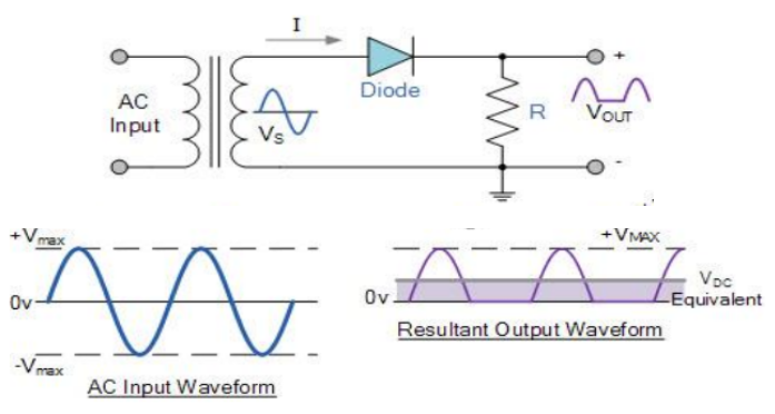
- The diode will be in the forward bias during the positive half cycle of the input AC signal. Hence, the current will flow through the load resistor (R), and we will get the output voltage across R is the same as the input voltage.
- The diode will be in reverse bias during the negative half cycle of the input AC signal. Hence, no current will flow through the load resistor (R), and we will get zero output voltage across R.
Full Wave Rectifier in Rectifier Circuit
In a Rectifier circuit, a rectifier is said to be a Full wave rectifier if it rectifies both half cycles in each full cycle of the input AC signal. We can classify the full-wave rectifiers into two types based on the number of diodes used and their configuration. Now, let’s discuss the following two types of Full-wave rectifiers.
- Center Tapped Full Wave Rectifier
- Full-wave Bridge Rectifier
Center Tapped Full Wave Rectifier
This Full wave rectifier consists of an AC voltage source in series with a resistor (Rs), a centre tapped transformer, two diodes (D1, D2), and a load resistor (R). The circuit diagram of a full-wave rectifier with a centre-tapped transformer and the corresponding input and output waveforms are shown in the following figures.
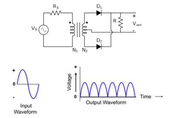
- The diode, D1, will be in the forward bias during the positive half cycle of the input AC signal. Hence, the current will flow through the load resistor (R), and we will get the output voltage across R to be the same as the input voltage.
- The diode, D2, will be in the forward bias during the negative half cycle of the input AC signal. Hence, the current will flow through the load resistor (R), and we will get the output voltage across R as the inverted version of the input voltage.
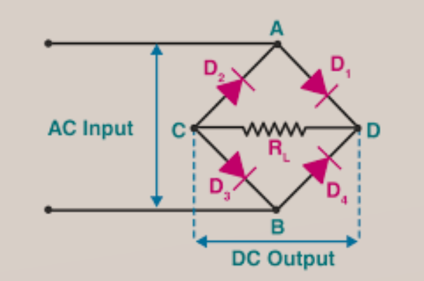
Full Wave Bridge Rectifier
This Full wave rectifier consists of an AC voltage source, transformer, four diodes (D1, D2, D3, D4), and a load resistor (R). The circuit diagram of the full-wave bridge rectifier and the corresponding input and output waveforms are shown in the following figures.
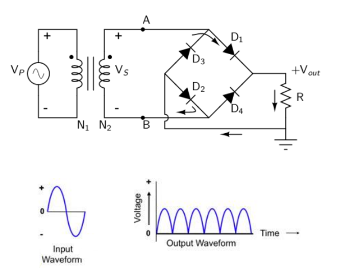
- The diodes D1 & D2 will be in the forward bias during the positive half cycle of the input AC signal. Hence, the current will flow through the load resistor (R), and the output voltage across R is the same as that of the input voltage.
The diodes D3 & D4 will be in the forward bias during the negative half cycle of the input AC signal. Hence, the current will flow through the load resistor (R), and we will get the output voltage across R as the inverted version of the input voltage.


