
- Home/
- GATE ELECTRONICS/
- GATE EC/
- Article
Power Amplifier
By BYJU'S Exam Prep
Updated on: September 25th, 2023

Power Amplifier is an amplifier that has a high-power-output stage. A power amplifier is a type of amplifier created to boost the strength of an input signal. An essential function of the output stage is to deliver the output signal to the load efficiently, which implies that the power dissipation at the output should be minimum.
Power amplifiers boost the input signal’s strength to a level that may drive numerous output devices, including speakers, headphones, RF transmitters, etc. This article gives an overview of the power amplifier and various classes of the power amplifier.
Table of content
-
1.
What is Power Amplifier?

-
2.
Classes of Power Amplifier
-
3.
Class A Power Amplifier
-
4.
Class B Power Amplifier (Complementary Symmetry Push-Pull Configuration)
-
5.
Class AB Power Amplifier
-
6.
Class C Power Amplifier
-
7.
Class D Power Amplifier (Switching Amplifier)
-
8.
Comparison of Different Classes of Power Amplifiers
What is Power Amplifier?
Power amplifiers are those amplifiers that increase the power of the input signal so that it can drive numerous output devices. Audio amplifiers and RF power amplifiers are examples of power amplifiers. These are designed to drive the loads directly, which is unlikely behavior than the voltage/current amplifiers.
Power amplifiers are also large signal amplifiers because the output power needed is very high. Preamplified signals are applied to the input of power amplifiers, also known as significant signals.
Classes of Power Amplifier
Power Amplifier Classes represent the amount of output signal that varies over one operation cycle for a complete input signal cycle. They can broadly be categorized as
- Class A
- Class B
- Class AB
- Class C
- Class D
Class A Power Amplifier
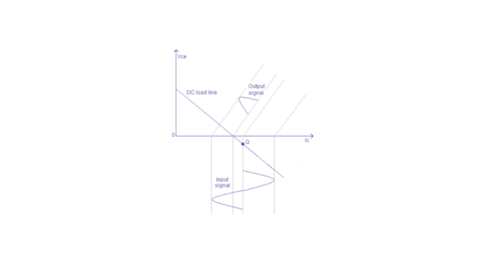
In Class A power amplifiers, the transistor is always ON, so the output current flows for the entire input cycle. The same transistor amplifies the waveform’s positive and negative portions. Class-A amplifier is biased at a level such that output may vary up and down without going to a high enough voltage to be limited by the supply voltage level or too low to approach the lower supply level, as shown below:
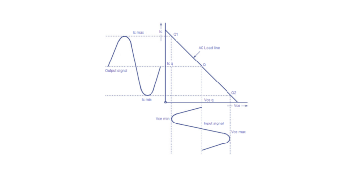
Class A amplifiers have a 360° conduction angle, the portion of the amplified waveform. Therefore, there is much less signal distortion, which improves high-frequency performance. Class A amplifiers can have many configurations. The most commonly used Class A amplifiers configurations are:
- Series fed Class A amplifiers
- Transformer coupled Class A amplifiers
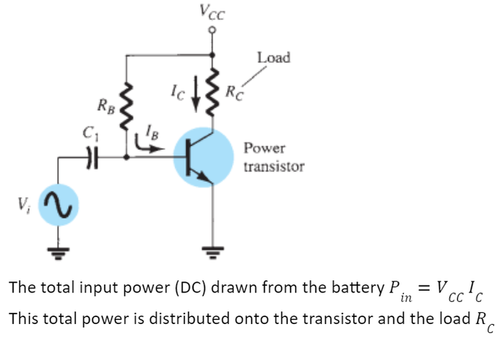
Series Fed Class A amplifiers
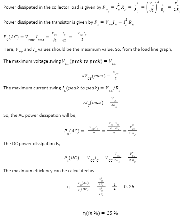
The transistors used in series fed class A amplifiers can operate in few to tens of watts. In this power amplifier, the transistor is still ON even when there is no input signal. Due to this, it produces a lot of heat and lowers the efficiency of class A amplifiers to 25%.
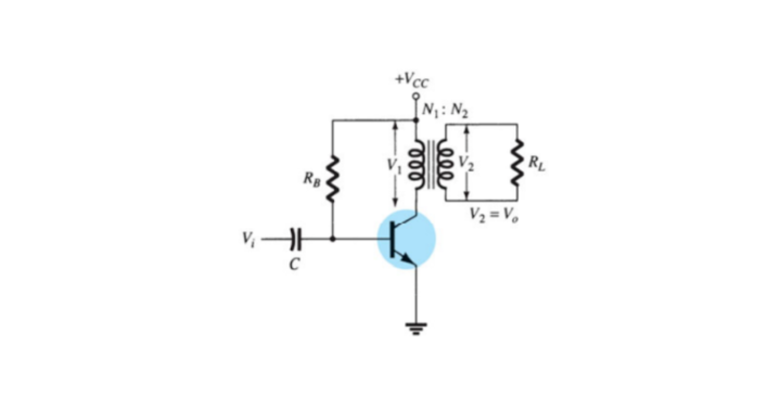
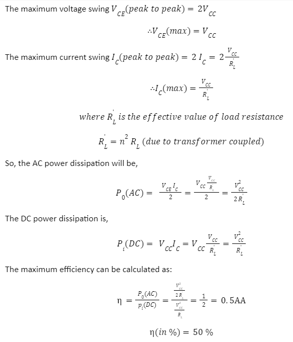
Transformer Coupled Class A amplifiers
In this power amplifier configuration, connecting the load through a transformer is to provide perfect impedance matching. Due to this, maximum power can be transferred to the load. This configuration of class A amplifiers can achieve efficiency up to 50% since it uses a transformer to couple the output signal to the load, as shown below:
The load line characteristics curve for a transformer coupled class A amplifiers can be drawn as:
![]()
Applications of Class A amplifiers
Class-A amplifiers are used in those applications which require very low power and low distortion, such as Guitars, Radio amplifiers, etc. Since the transistor in class A power amplifiers are always ON, they exhibit linear responses with minimal distortion.
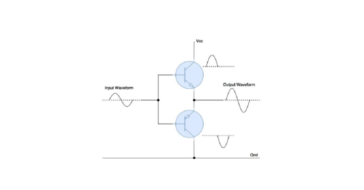
Class B Power Amplifier (Complementary Symmetry Push-Pull Configuration)
Class B power amplifiers have lower thermal issues than class A amplifiers. This family of amplifiers utilizes two complementary transistors rather than a single transistor to amplify the full waveform. The positive half is amplified by one transistor, and the negative half gets amplified by another transistor. As a result, each transistor conducts 180 degrees of the waveform, and collectively these two transistors can amplify the full signal. This is known as the Push-Pull configuration.
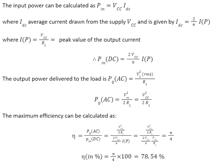
The transistors used in the push-pull configuration of class B power amplifiers can deliver the desired power to the load, increasing the efficiency of class A amplifiers. In class B amplifiers, the transistor is ON when an AC signal is applied.
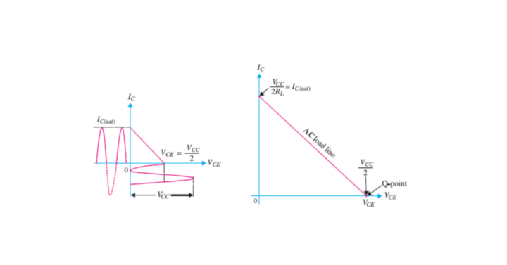
The Load line characteristics of class B amplifiers can be drawn as
Applications of Class B amplifiers
These power amplifiers are used in battery-powered devices like transistors and FM radios. A crossover distortion exists caused by the superposition of the two waveform portions in class B amplifiers. To lower the crossover distortion, the class AB amplifiers are introduced.
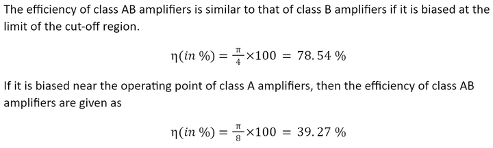
Class AB Power Amplifier
Class A and Class B amplifiers are combined to form class AB amplifiers. This class of amplifiers is created to lessen the problem of class A amplifiers (low efficiency) and class B amplifiers (crossover distortion).
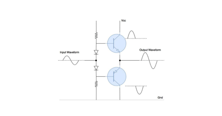
It keeps the high-frequency response of class A power amplifiers and the high efficiency of class B amplifiers. This class of amplifiers also requires push-pull configurations to get the full cycle at the output. Resistors and diodes provide a little bias voltage, which reduces the crossover distortion.
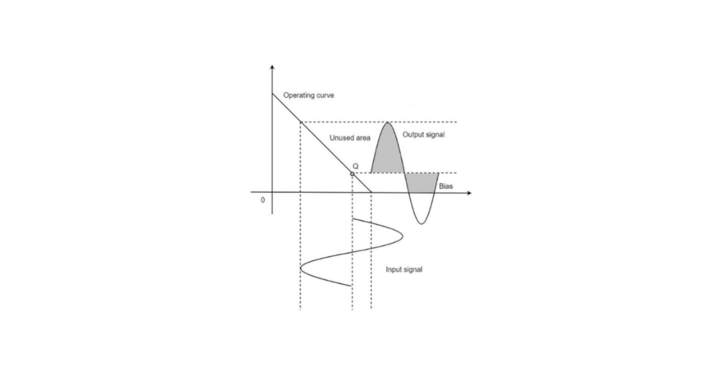
Class AB amplifiers are biased at a dc level above the current class B amplifiers and below the voltage of class A amplifiers. The output signal swing occurs between 180° and 360°. The output characteristics of class AB amplifiers can be drawn as:
Applications of Class AB amplifiers
These kinds of power amplifiers are utilized in studio monitors, amplifiers, hi-fi systems, etc. This configuration eliminates the crossover distortion caused in push-pull configurations of class B amplifiers.
Class C Power Amplifier
Class C power amplifiers have a conduction angle of < 90°. In other words, it compromises amplification quality for increased efficiency. This class of amplifiers is inappropriate for audio amplification since a smaller conduction angle means a higher level of distortion.
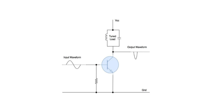
They are employed in the amplification of radio frequency signals and high-frequency oscillators. Class C power amplifiers use an additional tuned circuit to recover the original input signal from the pulsed output. The output characteristics of class C amplifiers can be drawn as
Applications of Class C amplifiers
Class C amplifiers use tuned radio frequency circuits to minimize distortion. These power amplifiers are typically found in radio frequency communication applications (Transmitter/Receiver).
Class D Power Amplifier (Switching Amplifier)
PWM modulated digital signals are amplified using power amplifiers of the classes D, E, F, and G. They fall into the switching power amplifier group because the output of these amplifiers is in continuously toggle mode. These power amplifier classes can theoretically achieve an efficiency of up to 90%-100%due to their simplicity.
Applications of Class D amplifiers
Class-D amplifiers are used in high-power applications because of their high efficiency, such as Woofers, high-power music systems, etc.
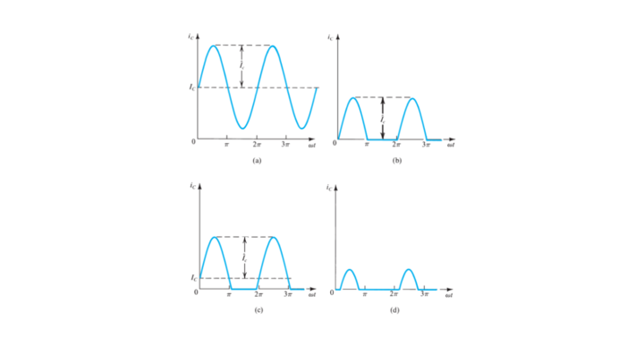
Comparison of Different Classes of Power Amplifiers
If a sinusoidal signal is applied at the input of power amplifiers, the following waveforms can be observed at the output of the respected power amplifiers.
|
Class |
Type |
Conduction Angle |
Efficiency |
Distortion (Properly Biased) |
|
A |
Linear |
360° |
25% – Series fed 50% – Transformer coupled |
No Distortion |
|
B |
Linear |
180° |
78.54% |
Crossover Distortion |
|
AB |
Linear |
Between 180° to 360° |
39.27% to 78.54% |
Small Distortion |
|
C |
Linear |
Less than 90° |
Greater than 80% |
Large Distortion |
|
D |
Switching |
0° |
Greater than 90% |
Intermodulation Distortion |


