
- Home/
- GATE ELECTRONICS/
- GATE EC/
- Article
What is a Norton’s Theorem?
By BYJU'S Exam Prep
Updated on: September 25th, 2023

Norton’s Theorem is the theorem we use for solving the given electrical network/ circuit and is also known as the Circuit theorem. Norton’s theorem is one of the important Network theorems. This theorem is useful for representing the given electric circuit into its equivalent circuit in the simplified form.
This article overviews Norton’s theorem and how to represent Norton’s equivalent circuit for the given circuit. Here, first, we will state Norton’s theorem. After that, we will see Norton’s theorem formula and procedure.
Table of content
Norton’s Theorem Statement
Norton’s theorem states that any 2-terminal linear and bilateral network or circuit having multiple independent and dependent sources can be represented in a simplified equivalent circuit known as Norton’s equivalent circuit.
Norton’s Theorem Circuit Diagram
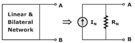
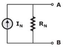
Norton’s equivalent circuit consists of Norton’s current source, IN in parallel with Norton’s resistance, RN. The parallel cthe ombination of current source and resistor is a practical current source. Hence, we can say that Norton’s equivalent circuit is nothing but a practical current source.
Procedure of Norton’s Theorem
It will take more time than the normal methods for finding the response of an element if the network/ circuit is having multiple sources and resistances. That time, we can use Norton’s theorem to find the response easily. Now, let’s see the steps for finding the response of an element when multiple sources and resistances are present in the network/ circuit by using Norton’s theorem.
- Step 1: Remove the element, where we are supposed to find the response from the given circuit. After the removal of the element, the terminals will be open.
- Step 2: Find the current flowing through the terminals of the circuit obtained in Step 1 after shorting them. This current is known as short circuit current or Norton’s equivalent current or Norton’s current, IN in short.
- Step 3: Replace all the independent sources with their internal resistances in the circuit obtained in Step 1.
- Step 4: Find the equivalent resistance across the open-circuited terminals of the circuit obtained in Step 3 indirect methods if there are no dependent sources. This equivalent resistance is known as Norton’s equivalent resistance or Norton’s resistance, RN in short.
- Step 5: If dependent sources are present, then we can find the equivalent resistance across the open-circuited terminals of the circuit obtained in Step 3 by using the Test source method. In the test source method, we will connect a 1V source (or 1A source) across the open terminals and will calculate another parameter current (or voltage). We will get the value of Norton’s resistance, RN by taking the ratio of voltage and current across the 2 terminals.
- Step 6: Draw Norton’s equivalent circuit by connecting Norton’s current, INin parallel with Norton’s resistance, RN.
- Step 7: Connect the element, where we are supposed to find the response at the open terminals of Norton’s equivalent circuit obtained in Step 6.
- Step 8: Find the response of that element by using laws or basic rules.
Norton’s Theorem Formula
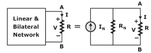
For the above-given circuit, Norton’s Theorem formula would be:
I = IN(RN/R+RN) & V= IN(RRN/R+RN).
Problems on Norton’s Theorem
Question 1: Find the current I of the following electric circuit using Norton’s theorem.
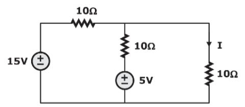
Answer: 2/3 A
Question 2: Find the voltage, V of the following electric circuit by using Norton’s theorem.
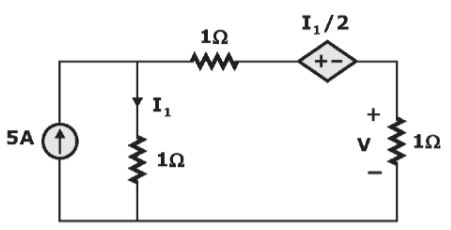
Answer: 1 volt
In this article, we discussed the statement of Norton’s theorem and how to apply this theorem to DC circuits. Similarly, we can apply Norton’s theorem for finding the response of an element when the circuit consists of multiple AC sources or the combination of DC and AC sources and multiple impedances/admittances.
| Important Topics for Gate Exam | |
| Heat Exchanger | Prims Algorithm |
| Rankine Cycle | Topological Sort |
| Inversion Of Mechanism | Hooke’s Law |
| Kaplan Turbine | Variable In C |
| Types Of Belt Drive | Superposition Theorem |


