
- Home/
- GATE ELECTRONICS/
- GATE EC/
- Article
Monostable Multivibrator
By BYJU'S Exam Prep
Updated on: September 25th, 2023

Monostable Multivibrators are also called on-shot multivibrators. They have one stable state and one monostable state, where a trigger (external signal) is required to enter the monostable state and return to the stable state. The circuit is primarily used as a timer, where the user will determine the response period.
In this article, we will discuss the construction of the circuit of a monostable multivibrator and its operation. We will also look into its different applications and cover its time and frequency calculations. As we know, multivibrators are wave generator circuits producing non-sinusoidal waveforms. A monostable multivibrator is one of these relaxation oscillators, sometimes also referred to as a pulse detector due to its ability to fluctuate on receiving a trigger.
Table of content
What is a Monostable Multivibrator?
There are two states in a monostable multivibrator: one permanent, which is stable, and one temporary, which is the quasi-stable state. A trigger pulse applied to the monostable at the right time changes its state from stable to quasi-stable state. A monostable multivibrator can not produce a square wave of its own like stable multivibrators because they remain in the quasi-stable state for a predetermined interval. Square waves can only be generated by external trigger pulses.
Monostable Multivibrator Diagram
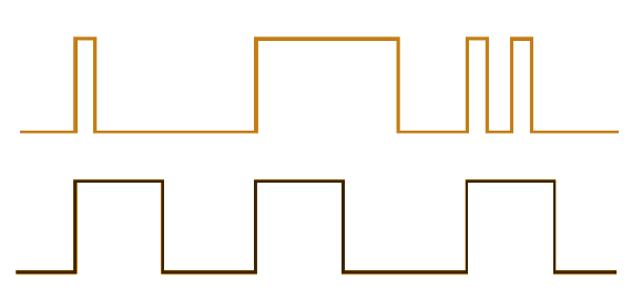
The above figure illustrates the functioning of the monostable multivibrator, where the green pulse represents the trigger pulse, and the red wave represents the response of the monostable multivibrator circuit. Notice that the response pulse changes its state for a brief duration on detecting a trigger and returns to its stable state.
Design and Working of Monostable Multivibrator
An external pulse is given when one of the transistors reaches a stable state. When the transistor changes its state, it remains in this quasi-stable or metastable state for a period, determined by the RC time constant values, before returning to the previous stable state.
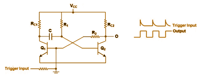
Circuit Diagram of a Monostable Multivibrator
Generally, monostable multivibrator circuits use passive components (resistors and capacitors) and active ones (transistors, Op-Amps, or 555 timers ICs). The following figure illustrates a circuit consisting of two bipolar junction transistors (BJTs) Q1 and Q2, one capacitor C, and four resistors R1C1, R2C2, R1, and R2.
Monostable Multivibrator PDF
Variations in the capacitors and resistors in the circuit can change the frequency of their output signal.
It consists of two transistors of equal collector loads, RL1 = RL2, reversing bias Q1 and keeping it at cut-off through the values of -Vgg and R2. VCC and R2 provide forward bias to Q1, which is maintained at saturation. A trigger pulse is given through C2 to obtain the square wave.
Operation of Monostable Multivibrator Circuit
At starting, there is no external trigger in this circuit, so one transistor will be in a saturation state, while the other will be in a cut-off state. Q1 will be in saturation, and Q2 in the cut-off state at negative potential until the external trigger operates, at which point Q2 will be in saturation mode.
When the external trigger is given to the input, the transistor Q1 will get turned on. Once it reaches saturation, the capacitor connected to the collector of Q1 and base of Q2 will turn the transistor Q2 off. Whenever the transistor Q2 is turned off, it is said to be in a quasi-stable state.
A capacitor charged to VCC will drive the Q2 again, and automatically Q1 will be turned off. Therefore, the capacitance charge time is directly proportional to the quasi-stable state of the multivibrator under external trigger conditions, i.e. (t=0.69RC).
Waveform of Monostable Multivibrator
A Monostable multivibrator’s time constant can be changed by varying the capacitor C1, resistor R1, or both. As the output frequency of the monostable multivibrator is always same as that of the trigger pulse input, the only difference is the pulse width, monostable multivibrators are generally used to widen pulses or delay time within a circuit. 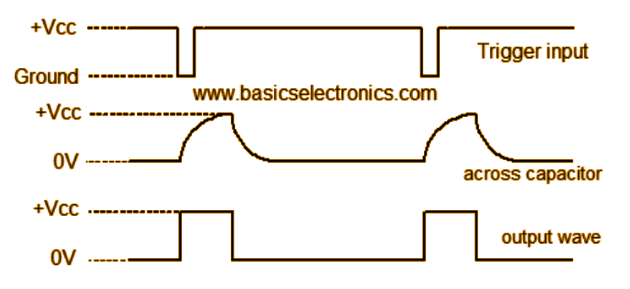
Frequency and Time Calculations of Monostable Multivibrator
The width of this output pulse depends upon the RC time constant. Hence it depends on the values of R1C1. The duration of the pulse is given by:
T=0.69 R1C1
Duty Cycle
It measures the ratio of time Tc during which the output is high to the total time of cycle T.

Thus, Duty Cycle = TOFF/(TOFF + TON) when the output is taken from the collector of the transistor T.
Applications of Monostable Multivibrator
Multivibrators, such as monostable multivibrator, are used in circuits such as televisions and control systems.
- In many cases, the falling part of the output pulse of MMV is used to trigger another pulse generator circuit, which produces a pulse delayed by a time T with respect to the input pulse.
- A Monostable multivibrator generates new, clean, and sharp pulses from distorted and worn-out pulses. For example, various pulses used in computers and telecommunication systems become somewhat distorted during use.


