- Home/
- GATE ELECTRICAL/
- GATE EE/
- Article
What is an Instrument Transformer?
By BYJU'S Exam Prep
Updated on: September 25th, 2023

When dealing with the measurement of operating voltages and currents in the power system, the conventional methods of measuring voltage and current with electromechanical instruments are far from reality. The instrument transformers are used to measure such high voltages and currents.
In this article, we will discuss the importance of an instrument transformer, the types of instrument transformers that are the current transformer and potential transformers, and the operating characteristics of an instrument transformer.
Download Formulas for GATE Electrical Engineering – Signals and Systems
Table of content
What is Instrument Transformer?
The instrument transformer is a combination of conventional measuring instruments and step-down transformers. An instrument transformer is used to extend the range of the Induction instrument.
Need for Instrument Transformer
In commercial metering, high values of currents and voltages are involved, so we cannot measure them with the voltmeters and ammeters of such high ratings. One may think that we can extend the range of the voltmeter and ammeter with the help of multipliers and shunt connections. Still, practically the instrument size will be significant, and cost-wise it is not even so wise to think about it. Apart from size and cost, we have critical operational difficulties with such extensions, that is the inaccuracy in A.C. circuits, the power consumed by the shunt is high for such significant ratings, and the critical issue is it is challenging to employ proper insulation for the instrument at the high voltages.
So, to measure these high voltages and currents, we must step down these quantities so that we can measure them with instruments of moderate size; this is exactly what the instrument transformers do. Apart from decreasing the quantities to be measured, the instrument transformer also provides isolation from the high voltage power circuits so that we can ensure the operator’s safety. Hence, the development of instrument transformers enables the measurement of high voltage such as 132 kV by using an instrument of a nominal 110 V rating, we can also measure a 1000 A of current with the help of a nominal 5 A ammeter.
Download Formulas for GATE Electrical Engineering – Electromagnetic Theory
What Principle Makes the Instrument Transformer Working?
Mutual induction is the principle that makes the instrument transformer work.
Basic Terminologies in Instrument Transformer
There is a standard terminology associated with the instrument transformers, such as the burden of the instrument transformer, transformation ratio (R), nominal ratio (Kn), turns ratio (n), and ratio correction factor (R.C.F); here, we will discuss the definitions of these terms.
Download Formulas for GATE Electrical Engineering – Electrical Machines
Transformation Ratio (R)
The transformation ratio is the ratio of the magnitude of the primary phasor to the secondary phasor of the instrument transformer.
>R=Magnitude of primary phasor/Magnitude of the secondary phasor
For the current transformer,
R=magnitude of primary current (Ip)/Magnitude of the secondary current (Is)
For the potential transformer,
R=magnitude of primary voltage (Vp)/magnitude of the secondary voltage (Vs)
Nominal Ratio (Kn)
The nominal ratio is the ratio of the rated value primary phasor to the rated secondary phasor of the instrument transformer.
For the current transformer,
Kn=Rated primary current (Ip rated)/Rated secondary current (Is rated)
For the potential transformer,
Kn=Rated primary voltage (Vp rated)/Rated secondary voltage (Vs. rated)
Turns Ratio(n)
If Np is the number of turns in the primary winding and Ns is the number of turns in the secondary winding of the instrument transformer then,
Turns ratio of the current transformer (C.T) is,
n=Ns/Np
Turns ratio of the potential transformer (P.T) is,
n=Np/Ns
Burden
The load connected on the secondary side, including the impedance of the measuring instrument, is known as the burden of the instrument transformer. The rated burden of the instrument transformer is the volt-ampere loading of the transformer, at which errors do not exceed a specified limit.
If Ze is the equivalent impedance on the secondary side of the instrument transformer that includes the secondary impedance winding, then.
Total secondary burden=Es2/Ze=Is2/Ze
Here Es is the secondary induced voltage of the instrument transformer.
If Vs. is the secondary terminal voltage of the instrument transformer and ZL is the impedance of the load connected to the secondary, then the secondary burden due to load=Vs2/ZL=Is2/ZL.
Ratio Correction Factor (R.C.F)
The ratio of the transformation ratio to the nominal ratio of the instrument transformer is known as the ratio correction factor.
R.C.F=RKn
Types of an Instrument Transformer
There are two types of instrument transformers, and they are namely
- Current transformer (C.T)
- Potential transformer (P.T), also known as the voltage transformer.
Current Transformer
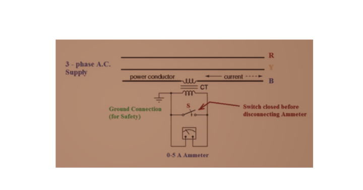
The instrument transformer connected in series with the high-power circuit to measure the current is known as the current transformer. Apart from the measuring applications, we can also use the current transformers to feed the protective relays in the power system protection. The below figure shows the basic circuit arrangement of the current transformer.

Unlike the power transformer, the primary current in the current transformer is not determined by the load connected in the secondary since the primary winding of the current transformer is connected in series with the current-carrying line. In contrast, the primary winding has a shunt connection with its source in the power transformer. Generally, the current ratings of secondary of current transformers are 5 A or 1 A.
- The primary winding of the current transformer has a smaller number of turns with thick conductors to withstand the high line currents, whereas the secondary side has a large number of turns.
- To protect the equipment in the event of insulation failure, one terminal of the C.T. secondary winding is grounded.
For the current transformers employed for the measuring applications, the saturation current will be 1.25 times the rated secondary current. Still, the C. T.s employed in protection applications must withstand high fault currents, so their core is designed with cold rolled grain oriented (CRGO) steel so that the C.T. can withstand these surges for a few more seconds and allow the relay to disconnect the faulty section.
Potential Transformer
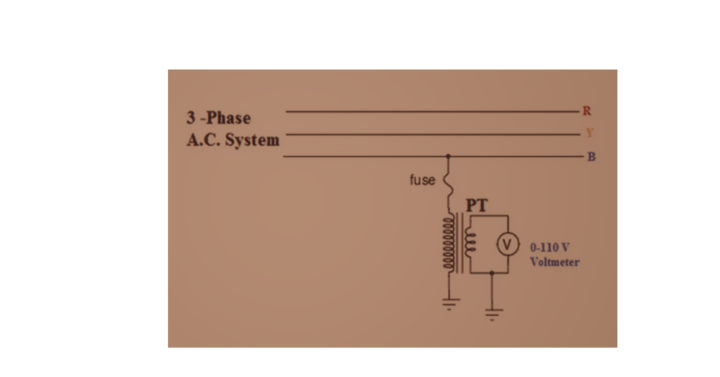
The primary winding of the potential transformers is connected in a shunt with high power circuit. The primary connection arrangement of the potential transformer is shown in the figure. The primary winding of the potential transformer has many turns, whereas the secondary winding has a smaller number of turns.

The secondary winding of the potential transformer is connected to the voltmeter, as shown above, as the voltmeter has a very high internal resistance, the operating condition of the potential transformer is almost similar to the open circuit transformer. To ensure the operator’s safety,r one terminal of P.T secondary is connected to the earth. Generally, the secondary voltage rating of the potential transformer is 110 V or 120 V line to line.
Errors in Current Transformer
Two errors occur with the current transformer; they are namely
- Ratio error
- Phase angle error
Ratio Error
Ratio error=[(Kn−R)/R]×100
⇒Ratio error=(Kn/R−1)×100
⇒Ratio error=(1/R.C.F−1)×100
Phase Angle Error
For an ideal instrument transformer, the angle between the primary and secondary current will be 180°, but in practice, this angle is less than 180° which is 180°−θ.
Causes of Errors in Current Transformer
The causes of errors in the current transformer are,
- Losses in the core of the transformer.
- Losses are associated with winding resistance.
- Flux leakage in the transformer.
- Core saturation.
Reduction of Errors in Current Transformer
The errors in the current transformer can be reduced by using high permeable materials for the core construction, that is, CRGO steel, nickel-ferrous alloy, and silicon steel stampings, to minimize core losses. In addition, reduce the air gap between the primary and secondary windings to avoid leakage flux.
Why Should the Secondary Winding of the C.T not be Open-Circuited?
In a power transformer, the primary current depends on its secondary current. If secondary is open-circuited, the primary current also reduces to the no-load current value. Whereas in the current transformer (C.T), the primary winding is connected in series with the power circuit, so the primary current is constant irrespective of the condition of the secondary winding; hence the primary M.M.F is constant.
During regular operation, the secondary M.M.F will oppose the primary M.M.F as per Lenz’s law. If we suddenly disconnect the C.T secondary, there is no counter force for the primary M.M.F, which is constant. This primary M.M.F will increase the core flux and causes it to saturate, or if the core is still capable, it will produce a vast flux linkage at the C.T secondary,y, which has many turns. This flux linkage will produce a high voltage across the secondary, damaging the insulation and harming the operator responsible for the secondary winding opening. To avoid this, before removing the burden from C.T, short-circuit is done using an earth switch.
This short circuit will not affect the C.T, as the C.T is designed to operate with an ammeter across it; we know that the internal resistance of the ammeter is almost negligible, so the C.T is generally designed to operate with a negligible resistance almost equivalent to the short circuit across its secondary winding.
Advantages of Instrument Transformer
The instrument transformers are more advantageous than the shunts or multipliers used for the instrument extension. These are a few such advantages.
- We can measure high quantities of voltages and currents with the instruments of moderate ratings.
- The measuring circuit is isolated from the high-power circuit.
- The readings of instrument transformers don’t depend on circuit parameters like resistance, inductance, and capacitance. In contrast, these parameters will affect the reading if we use shunts and multipliers for the instrument extension.


