
- Home/
- GATE ELECTRICAL/
- GATE EE/
- Article
What is an Induction Motor?
By BYJU'S Exam Prep
Updated on: September 25th, 2023
An induction motor is one in which torque is produced by electromagnetic induction. The rotor can be a squirrel cage rotor or a wound rotor. If I say “9 out of 10 motors running at this moment are induction motors” that would not be an exaggerated statement since they found applications in the range from a few watts rating domestic motors to hundreds of kilowatts industrial drive due to their simple and robust construction and rare demand of any maintenance.
In this article, we will discuss, how the induction motor is different from other motor constructions in electrical engineering, that is the DC motor and synchronous motor, the basic constructional features of the induction motor along with its operating principle. Candidates can go through the study notes on induction motor while preparing for GATE and other related examinations.
Table of content
What is an Induction Motor?
In contrast, the counterparts synchronous and DC motor involves complex design constraints and regular monitoring. The DC motors found a rare use in the form of some constant speed industrial drives with a need for exquisite control of speed but still they need converters to feed them, and the main issue with the DC motors is the commutator, that makes the design very complicated in addition to that it needs a proper design of rotor and stator winding, but most of the induction motors are using the squirrel cage rotor in which the rotor bars are simply short-circuited at both ends.
If you consider the synchronous motor that needs the excitation at the stator as well as the rotor to maintain the field winding, for the field excitation again we need either the static converter or a DC generator to supply the Direct current. The polyphase induction motor is a singly excited machine, there is no need for a commutator. The stator of the motor is fed from the A.C mains and the rotor will energize from the stator by means of electromagnetic induction.
Construction of an Induction Motor
Like any other rotating electrical machine, the induction motor contains a stationary part stator that accommodates the 3-phase winding in its slots, and the rotating component is a rotor that drives the mechanical load.
Stator
It contains an outer frame that acts as a protective covering for the entire machine, made of cast iron or aluminum and the hallow stator core that is made up of high-grade silicon steel laminations containing slots at the inner periphery. The slots contain the three-phase winging that is uniformly distributed among them.
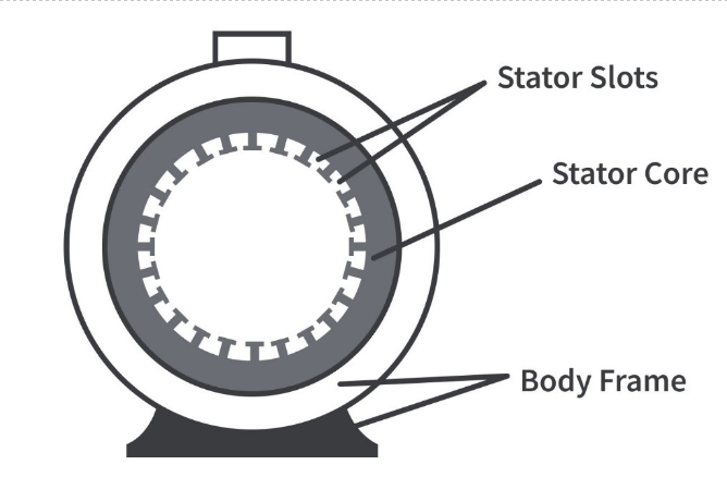
Generally, there are three types of slots namely
- Open type slots
- Closed type slots
- Semi-closed type slots
If we opt for the open type slots it will increase the effective air gap between the stator and rotor, which demands a high magnetizing current, but they can help in the prevention of leakage flux as they will offer the reluctance to the leakage path, and it is simple to attend for the maintenance and repair of this kind of slots. On the other hand, if we opt for the closed type slots, they are in complete contrast to the open type slots, they can reduce the magnetizing current, but the issue is the significant leakage of the flux can overshadow that advantage. Hence to maintain a fine balance between the magnetizing current and flux leakage we generally prefer the semi-closed slots.
Rotor
There are two-type two-types of rotors
- Squirrel-cage rotor
- Slip-ring rotor
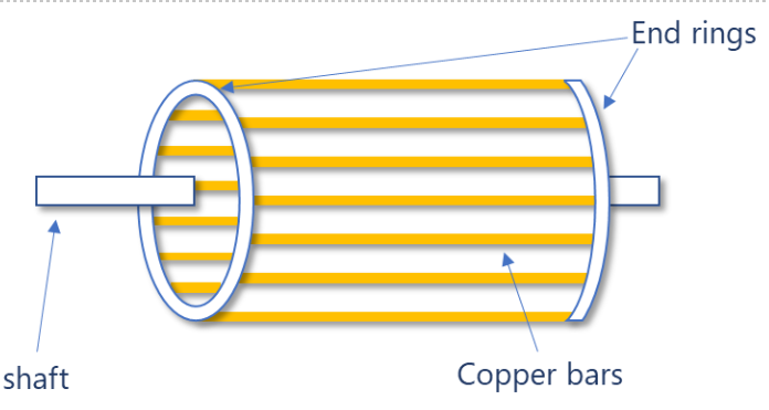
Squirrel Cage Rotor
The squirrel cage rotor contains a cylindrical rotor core made of steel or silicon steel laminations that are thick as the induction motor will operate at low-frequency conditions (50 Hz or 60 Hz). It contains the semi-closed slots that contain the cast aluminum or the alloy copper bars solidly short-circuited at both ends using two metal rings. The slots of the rotor are skewed to reduce the effects of crawling and cogging. The slots are designed for less depth to minimize the rotor reactance that affects the maximum torque rating of the motor since
Tmax∝1/2X2
This rotor offers superior running characteristics, but the major drawback of this motor is its low starting torque.
Slip Ring Rotor
The rotor core of the slip ring rotor appears like the armature core of a DC motor. It is made up of silicon steel laminations with semi-closed slots which are skewed. The rotor windings are placed in slots that are an exact mirror image of the stator winding but preferably star-connected. In each phase of the rotor inserted with an external resistance of suitable value to increase the starting torque as the starting torque of the induction motor is proportional to its rotor resistance up to a suitable value.
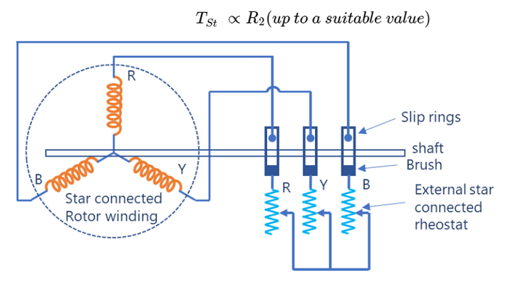
Under running conditions, the slip ring will be lifted out and short circuit using a metal collar arrangement in the shaft. The rotor is essentially designed with the same number of poles as the stator, unlike the squirrel cage rotor which can be designed with any number of poles. The slip ring rotors are rarely preferred in applications that demand high starting torque.
- Around 90 percent of industrial motors and all single-phase induction motors are of the squirrel cage type only.
Rotating Magnetic Field (R.M.F)
We must be aware of the concept of a rotating magnetic field to understand the operation of the induction motor. When a three-phase supply (with 120°time displacement) is given a three-phase winding (with 120°space displacement), the three-phase currents will produce the three-phase fluxes to produce a net flux that rotates at the synchronous speed in a particular direction with a resultant magnitude of 1.5 times the peak value of the fundamental flux, the direction of rotation will depend on the phase sequence.
Working Principle of an Induction Motor
The basic principle involved in the operation of an induction motor is electromagnetic induction just like the transformer. Hence often the induction motor is referred to as the rotating transformer.
When a 3-phase supply is given to the 3-phase winding a rotating magnetic field will produce and rotates at a synchronous speed. The rotating magnetic field will cut the stationary rotor conductors at a relative speed of Nr(=Ns−0)to induce voltage and produce the current in the rotor as it is essentially a closed circuit. Therefore, the rotor will start the rotation, and the direction of rotation of the rotor can be explained with Lenz’s law. According to Lenz’s law, the result (rotor rotation) will oppose the cause (relative speed), hence the rotor starts to oppose the relative speed by rotating in the direction of R.M.F. and start accelerating to meet the speed of R.M.F (Ns), but could not meet R.M.F and slips back to run with a speed near to the synchronous speed. Like this, in the entire operation, it tries to reach but falls back due to the rotor copper loss occurring inside the rotor. In our lectures, we can discuss how the rotor copper losses pave the way for the operation of an induction motor, what are its torque-slip characteristics, etc.
Slip
It is the number representing the relative speed between the rotating magnetic field and the rotor. It is defined as the difference between synchronous speed and the actual speed of the rotor expressed in the percentage of synchronous speed.

Here
- f= Operating frequency of the induction motor
- P= Number of poles in the stator design.
| Important Topics for Gate Exam | |
| Feedback Amplifier | Fermi Level |
| Floating Point Representation | Flow Measurement |
| Fluid Pressure | Fluid Properties |
| Flywheel | Full Subtractor |
| Gear Train | Incidence Matrix |


