Time Left - 15:00 mins
GATE 2023 Analog Circuits Quiz 7
Attempt now to get your rank among 29 students!
Question 1
The emitter-bias configuration of figure shown below has following specifications:
ICQ = 0.5 IC sat, IC sat = 8 mA, VC = 18 V and β = 110. Determine RC,RE and RB

ICQ = 0.5 IC sat, IC sat = 8 mA, VC = 18 V and β = 110. Determine RC,RE and RB
Question 2
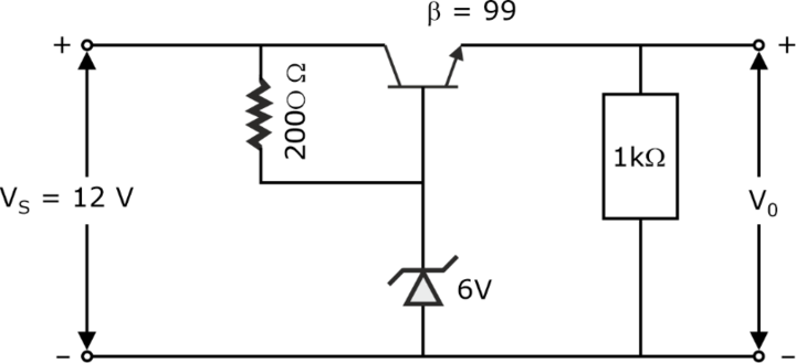
In the voltage regulator circuit in figure the maximum load current IL that can be drawn is 
Question 3
In the shunt regulator shown below, the VZ = 8.2 V and VBE = 0.7 V. Find the regulated output voltage VO .

Question 4
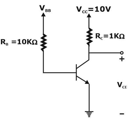
In the voltage regulator circuit shown in figure, the power dissipation in zener diode approximately is
Question 5
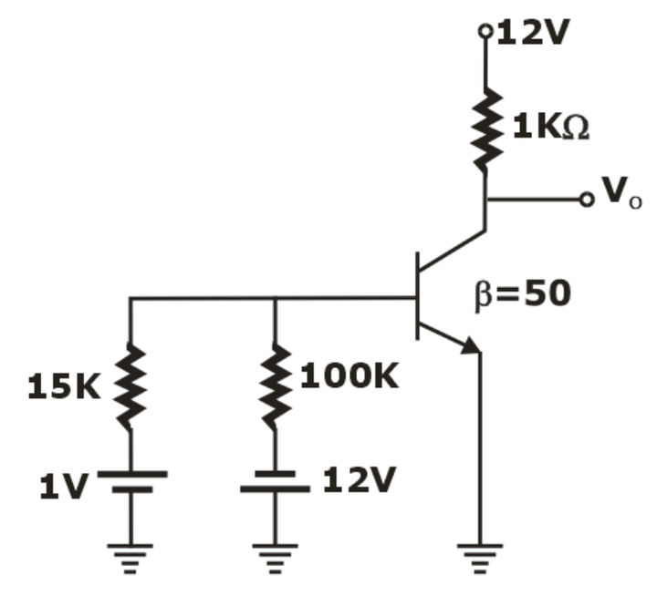
For the circuit shown in figure below, the transistor is operated in the _________ region and its output voltage is ___________.
Question 6Multiple Correct Options
The BJT shown below has ,
, and
and . Then
- 29 attempts
- 0 upvotes
- 0 comments
Jul 4ESE & GATE EC

