
Flow Through Pipes: Major and Minor Losses
By BYJU'S Exam Prep
Updated on: September 25th, 2023

In the “Flow through pipes” topic, we will understand the different flow characteristics when the flow occurs into the pipes. Based on these characteristics of flow through pipes, flow can be categorized into the laminar flow and turbulent flow. In this chapter, different losses that occurred in the pipe flow will be estimated.
Flow Through Pipes PDF
The energy at the exit point is calculated based on the different losses in the pipe flow. These losses that occur during the flow through pipes are broadly classified into major types of losses and some minor losses. This article contains basic notes on the “Flow through pipes” topic of the “Fluid Mechanics & Hydraulics” subject.
Table of content
What is Flow Through Pipes?
Flow through pipes is an important topic in fluid mechanics. It is important to understand the different types of losses that occur during the flow through pipes for the GATE CE exam. Based on different losses, the total energy at the exit point of the pipe is calculated.

Major Losses in Flow Through Pipes
In flow through pipes, losses that occur in the pipe flow are a very important parameter for the design. These losses include the major loss due to friction and some minor losses. Darcy Weisbach’s equations can calculate major losses in flow through pipes. These are explained as follows.
Loss of head due to friction
hf = 4fLv2/2gd
where,
- L = Length of pipe,
- v = Mean velocity of flow
- d = Diameter of pipe,
- f = Coefficient of friction
or hf = f’Lv2/2gd
f’ = 4f
friction factor for laminar flow, f = 64/ Re
Coefficient of friction, f = 16/ Re
For turbulent flow, the coefficient of friction
f = 0.079/(Re)0.25
Chezy’s Formula: In fluid dynamics, Chezy’s formula describes the mean flow velocity of steady, turbulent open channel flow.

v= c √mi, c= Chezy’s Constant = √(8g/f)
Relation between Coefficient of Friction and Shear Stress

We get
f = 2τ0/ρv2
where,
- f = Coefficient of friction
- τ0 = Shear stress
Minor Losses in Flow Through Pipes
Another type of head loss, minor loss, is induced for the following reasons. These losses are used in the GATE CE question paper to create the NAT-based questions.
Loss due to Sudden Enlargement
Head loss, hL = (v1 – v2)2/ 2g
Loss due to Sudden Contraction
Head loss, hL = 0.5 v22/ 2g
Remember, v2 is the velocity at a point in the contracted section.
Loss of Head at Entrance to Pipe
Head loss,
hL = 0.5V21/2g
Loss at Exit from Pipe
Head loss,
hL = V21/2g
Combination of Pipe Connections
Pipes may be connected in series, parallel or in both. Let’s see their combinations.
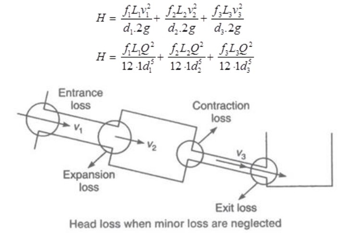
Pipe in Series: As pipes are in series, the discharge through each pipe will be the same.

Q = A1v1 = A2v2 = A3v3
Total loss of head = Major loss + Minor loss
H = hL1 + hL2
Major loss = Head loss
due to friction in each pipe
hL1 = hf1 + hf2 + hf3
While, minor loss = Entrance loss + Expansion loss + Contraction loss + Exit loss

If minor losses are neglected, then,
Pipes in Parallel: In this, discharge in the main pipe is equal to the sum of discharge in each parallel pipe.

Hence, Q = Q1 + Q2
The head loss in each parallel pipe is the same,
hf1 = hf2
where hf1 and hf2 are head loss at 1 and 2, respectively.
Equivalent Pipe: A compound pipe with several pipes of different lengths and diameters to be replaced by a pipe with a uniform diameter and the same length as a compound pipe is called an equivalent pipe.

(where, L = L1 + L2 + L3)
If f = f1 = f2 = f3
Then,

Hydraulic Gradient Line (HGL) and Total Energy Line (TEL)

HGL → It joins the piezometric head ((p/ρg) + z) at various points.
TEL → It joins the total energy head at various points:
{((p/ρg) + z) + (v2/2g)}
Note: HGL is always parallel but lower than TEL.
Power Transmission Through Pipe (P)
When a pipe is connected to a water tank, Power applied by a pipe flow at the outlet end depends upon the flow characteristics, pipe characteristics, etc. It will be explained below in detail for different cases.

Pideal = ρgQH
Pactual = ρgQ(H – hf); hf = head loss
Efficiency, η = (H – hf)/H
Power delivered by a given pipeline is maximum when the flow is such that one-third of the static head is consumed in pipe friction. Thus, efficiency is limited to only 66.66%
Maximum efficiency, ηmax = H/3.
Water Hammer: When a liquid is flowing through a long pipe fitted with a vale at the end of the pipe, and the valve is closed, suddenly, a pressure wave of high intensity is produced behind the valve. This high-intensity pressure wave has the effect of hammering action on the walls of the pipe. This phenomenon is known as a water hammer.
The intensity of pressure rise due to the water hammer
P = -ρLν/t
When the valve is closed gradually, when valve closes suddenly with a rigid pipe.
P = ν × (Kρ)0.5
When the valve closed suddenly with a plastic pipe
ρ = ν ×[ρ/{(1/K) + (D/Et)}]0.5
If the time required to close the valve
t > 2L/C ⇒ Valve closure is said to be gradual.
t < 2L/C ⇒ The valve closure is said to be sudden.
Where,
- L = Length of pipe
- D = Diameter of pipe
- C = Velocity of pressure wave produced due to water hammer = √(K/P)
- v = Velocity of flow
- K = Bulk modulus of water
- E = Modulus of elasticity for pipe material.
- t = Time required to choose the valve.


