
- Home/
- GATE MECHANICAL/
- GATE ME/
- Article
Deflection of Beams: Deflection Formula, Deflection Unit
By BYJU'S Exam Prep
Updated on: September 25th, 2023

Deflection of Beams is the representation of deflection of the structure from its original unloaded position. Beams are widely used in different types of structures. Therefore, it is very important to know how to predict the deflection of beams when different types of load and their load combinations are applied.
It is very important to limit the deflection of beams as too much deflection might cause damage to other parts of the structures. If too much deflection of the beam is allowed, it will fail the serviceability criteria; even though the stresses acting in the beam are low and safe, the structure will fail to serve the purpose of its construction. Let us know more about the deflection of beams discussed in the upcoming sections.
Table of content
What is the Deflection of Beams?
The deflection is measured from the beam’s original neutral surface to the deformed beam’s neutral surface. The configuration assumed by the deformed neutral surface is known as the elastic curve of the beam.
Deflection of Beams Definition
Deflection of beams is the transverse deformation that occurs due to the shear force and bending moment. The deflection of beams due to the shear force is insignificant compared to the deflection of beams due to the bending moment. Therefore, the deflection of beams due to shear force is ignored.
Let us now see the slope and deflection of beams in brief.
- The slope of a Beam: The slope of a beam is the angle between deflected beam to the actual beam at the same point.
- Deflection of Beam: Deflection is defined as the vertical displacement of a point on a loaded beam. Many methods determine the slope and deflection at a section in a loaded beam.
The maximum deflection occurs where the slope is zero. The maximum deflection position is found by equating the slope equation to zero. Then the value of x is substituted in the deflection equation to calculate the maximum deflection.Deflection of Beams is an essential topic in the Strength of Materials subject.
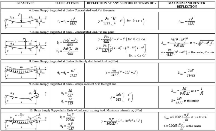
Deflection of Beams Formula
The deformed shape of the bean is known as an elastic curve. The slope and deflection of beams formula for some standard cases are listed below. These formulae can be directly for solving many problems of deflection of beams.
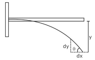
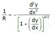
y is the vertical deflection of the beam. The objective of the beam is defined as the shape given by:
θ= dy/dx
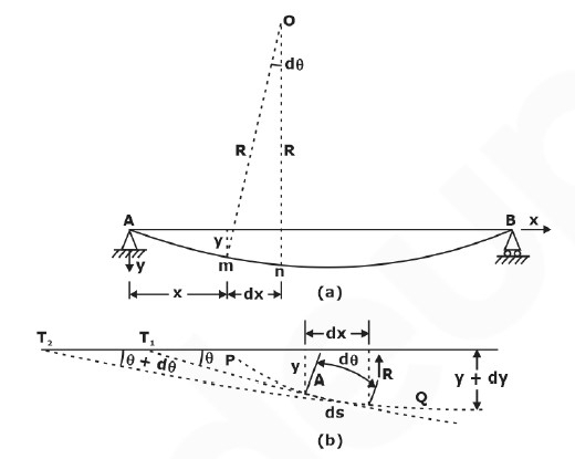
The moment Curvature equation is used to calculate the deflection of beams.
1/R=M/EI
Where
- M = Bending Moment
- R = Radius of Curvature of deformed shape
- EI = Flexural Rigidity of the beam
- 1/R = Curvature of beam
Deflection Differential Equation
d2y/dx2 = M/EI
(a)
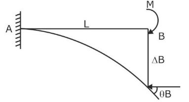
ΘB= ML/EI
∆B= ML2/2EI
(b)
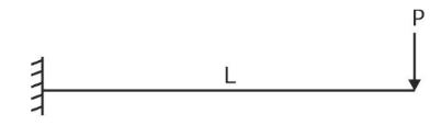
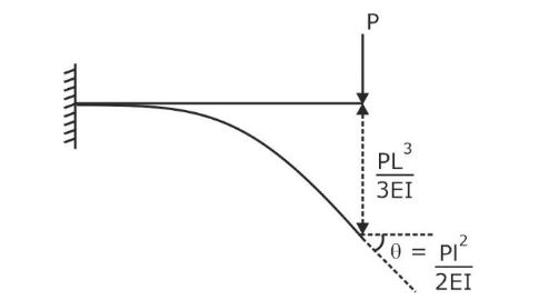
ΘB= PL2/2EI
∆B= PL3/3EI
(c)
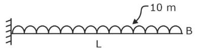
ΘB= WL3/6EI
∆B= WL4/8EI
DIFFERENTIAL EQUATION OF THE DEFLECTION CURVE OF BEAM
Deflection of Beams Formula for Cantilever Beams:

Deflection of Beams Formula for Simply supported Beams:
Methods of Determining Beam Deflections
There are various methods through which deflections of beams and structures can be found depending upon the type of load and nature of the beam. Some important methods to determine the deflection of beams are:
- Double Integration Method
- Macaulay’s Method
- Moment Area Method
- Conjugate Beam Method
Double Integration Method
The double integration method is suitable for prismatic beams having constant EI. This method is suitable when the bending moment equation remains constant throughout the length of the beam. According to the double integration method,
EId2y/dx2 =Mx
Where
EI = Flexural Rigidity
Mx = Bending Moment at Section
Integrating the above equation,
EIdy/dx= ∫Mx+ c1
This gives the equation of slopes where dy/dxis slope or rotation.
Integrating the above equation,
EI.y= ∬Mx+ ∫c1+ c2
Where y is deflection.
Macaulay’s Method
Macaulay’s Method is an improvement over the double integration method. It becomes difficult to solve deflections of the beam that need to be split into many sections. Therefore, this method is used where there is no need to split the beam. This method is suitable for prismatic bars having different bending moments at different cross-sections.
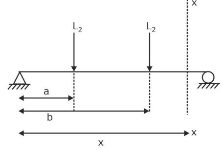 Consider the above beam carrying two point loads L1 and L2 at a distance of ‘a’ and ‘b’ from the left support. Consider a section x-x at a distance of x from left support. Finding moment about x-x:
Mx= RAx- L1(x-a)- L2(x-b)
EId2y/dx2=RAx- L1(x-a)- L2(x-b)
Integrating the above equation,
EI y= RAx3/6+ c1x+ c2-[L1(x-a)3/6]- [L2(x-b)3/6]
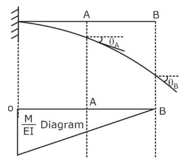
Moment Area Method
The moment area method is used when we need to analyze a beam in which we are interested in calculating the slope and deflection of the beam at a single location. This method is suitable for prismatic and non-prismatic members. This method is based on the area under the bending moment diagram.
Theorem 1
Change in slope from section A to section B B-A will equal the area of the M/EI diagram between ΘA and ΘB.
ΘB-ΘA=A
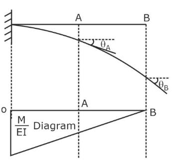 Theorem 2
The deflection of section B concerning the tangent at section A is the area of the M/EI diagram between A and B about point B.
Conjugate Beam Method
A conjugate beam is an imaginary beam whose loading diagram is the M/EI diagram of the real beam. The conjugate beam method is suitable for both prismatic and non-prismatic members; the only requirement is the M/EI diagram should not be completed; it must be easy to determine the area and centroid of the M/EI diagram. If the M/EI diagram is positive, then loading in the conjugate beam will be upward. If the M/EI diagram is negative, then loading in the conjugate beam will be downward.
Theorem 1
The slope at any section on the real beam becomes a shear force at the corresponding section on the conjugate beam. The shear force diagram of the conjugate beam represents the slope diagram of the real beam.
Theorem 2
The deflection at any section on the real beam becomes a bending moment at the corresponding section in a conjugate beam. The bending moment diagram of the conjugate beam represents the deflection diagram of the real beam.
Method of Superposition: The method of superposition, in which the applied loading is represented as a series of simple loads for which deflection formulas are available. Then the desired deflection is computed by adding the contributions of the component loads(principle of superposition).
The most direct formula is used in questions. Hence it is advised to look for the beam deflection formula, which is directly asked from this topic, rather than going for long derivations.
Deflection for Common Loadings
1. Concentrated load at the free end of the cantilever beam (origin at A):
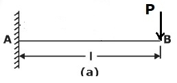
Maximum Moment, M=−PL
The slope at the end:θ=PL2/2EI
Maximum deflection:δ=PL3/3EI
Deflection Equation(y is positive downward): EIy = (Px2)(3L−x)/6
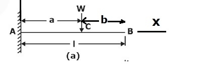
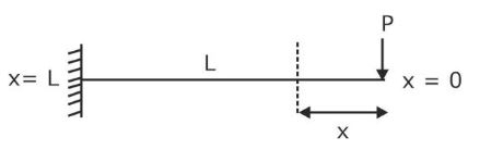
2. Concentrated load at any point on the span of a cantilever beam
Maximum Moment:M = -wa
The slope at the end:θ = wa2/2EI
Maximum deflection:>δ = wa3(3L−a)/6EI
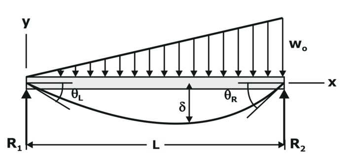
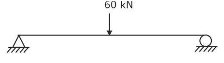
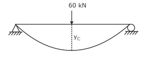
Deflection Equation(y is positive downward), 3. Uniformly distributed load over the entire length of a cantilever beam Maximum Moment: M = −wL2/2 Slope at end: θ = wL3/6EI Maximum deflection:δ = wL4/8EI Deflection Equation (y is positive downward), 4. Triangular load, full at the fixed end and zero at the free end Maximum Moment: M=−wL2/6 Slope at the end: θ = wL3/24EI Maximum deflection, δ = wL4/30EI Deflection Equation: (y is positive downward), 5. Moment load at the free end of a cantilever beam Maximum Moment: M = −M The slope at end:θ=ML/EI Maximum deflection:δ=ML2/2EI Deflection Equation (y is positive downward), 6. Concentrated load at the midspan of a simple beam Maximum Moment: M=PL/4 Slope at end:θA=θB= WL2/16EI Maximum deflection:δ=PL3/48EI Deflection Equation (y is positive downward), 7. Uniformly distributed load over the entire span of a simple beam Maximum Moment:M = wL2/8 The slope at the end:θL=θR=wL3/24EI Maximum deflection:δ=5wL4/384EI Deflection Equation (EIy=wx(L3−2Lx2+x3)/24 9. Triangle load with zero at one support and full at the other support of the simple beam Maximum Moment:M = woL2/9√3 Slope at the end, θL=7wL3/360EI θR=8wL3/360EI Maximum deflection:δ=2.5wL4/384EI at x = 0.519L Deflection Equation (y is positive downward), 10. Triangular load with zero at each support and full at the midspan of a simple beam Maximum Moment: M = wL2/12 The slope at the end, θL = θR = 5wL3/192EI Maximum deflection: δ = wL4/120EI Deflection Equation(y is positive downward), Problem 1: What is the slope and direction of a cantilever beam at the free endpoint load acting at the free end? Solution- The differential equation for deflection M= -Px EId2y/dx2=-Px ∫EId2y/dx2= ∫-Px EIdy/dx= -Px2/2+ c1 Boundary Conditions at x=L, dy/dx = 0, c1= PL2/2 EIdy/dx= -Px2/2+ PL2/2 Integrating this, we get, EIy= -Px3/6+ PL2x/2+ c2 Boundary condition x=L, y=0 c2= -PL3/3 EIy= -Px3/6+ PL2x/2- PL3/3 Slope and deflection at the free end Slope dy/dx= PL2/2EI Deflection y= PL3/3EI Problem 2: Simply supported beam of span 6m is loaded as shown in the figure. I = 78 x 106 mm4 E = 2.1 x 10⁵ N/mm2. Find the central deflections. Solution- We know that yc= WL3/48EI= 60 × 103 ×60003/(48 ×2.1 × 105 ×78 × 106)= 16.48mm Problem 3: A simply supported beam of a span of 5m carrying a load of 10N/mm2. Given E= 104 N/mm2. The maximum permissible bending stress is 8N/mm2, and the maximum deflection of the beam is 1 cm. Determine the width and depth of the beam. Solution- (σb)max= Mmax/z= 8 10 × 50002 ×6/(8 ×BD2)=23437500 mm3 Maximum Deflection= 5WL4/384EI 5WL4/384EI=10mm 5WL4/384 ×104 ×B × D3=10mm BD3=9765625000 mm4 D= BD3/BD2= 9765625000/23437500= 416.67 mm BD2=23437500 B = 134.99mm If you are preparing for GATE and ESE, avail Online Classroom Program to get unlimited access to all the live structured courses and mock tests from the following link:
EIy = Px2(3a−x)/6for0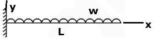
EIy=wx2(6L2−4Lx+x2)/120L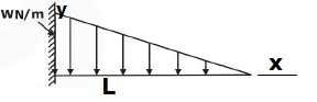
EIy = wx2(10L3−10L2x+5Lx2−x3)/120L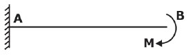
EIy=Mx2/2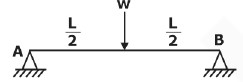
EIy=Px{(3/4)L2−x2)}/12 for 0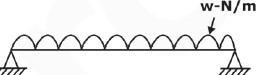
EIy = wx(7L4−10L2x+3x)/360L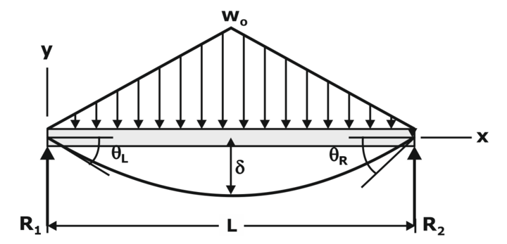
EIy=wox(25L4−40L2x2+16x4)/960L for 0Deflection of Beams Questions
Online Classroom Program
BYJU’S Exam Prep Test Series


