
Column and Strut: Common Difference of Strut & Column
By BYJU'S Exam Prep
Updated on: September 25th, 2023

Columns and Struts are any structural members experiencing axial compression due to axial or longitudinal loads. A column is a vertical member which is used in structures for supporting the horizontal load over it. A strut can be a horizontal/ vertical/ inclined member that is subjected to axial compression load. It is comparatively a shorter column.
In this article, we will try to learn about columns and struts in detail, the basic differences between them, and the classification of columns. We will also see how columns are further divided in terms of their slenderness ratio.
Table of content
-
1.
Difference Between Columns and Struts

-
2.
Effective Length of Columns and Struts
-
3.
Slenderness Ratio
-
4.
Classification of Columns based on Slenderness Ratio
-
5.
Elastic Instability
-
6.
Assumptions for Euler’s Equation for Elastic Instability
-
7.
Rankine’s Theory For Columns
-
8.
Columns and Struts Solved Problems
Difference Between Columns and Struts
The basic difference between columns and struts is that a column is a vertical member designed to carry axial or longitudinal loads. In contrast, a strut is a horizontal/inclined/vertical member designed to take axial or longitudinal loads. Columns are supported by fixed supports at both ends, while struts are supported by hinged or pinned joints at both ends, as struts are generally used in a truss.
In columns, failure is generally due to buckling, while in struts, failure is generally due to crushing. Columns have a more slenderness ratio, while struts have a less slenderness ratio. Columns can carry only both compressive and tensile loads.
Effective Length of Columns and Struts
The load-carrying capacity of columns and struts, i.e., compression members, depends on the length of the member, the cross-sectional area of the member, and the type of support. The effective length of a column is the distance between two points on a column where the bending moment is zero. It is written as the product of effective length factor and unsupported length.
Effective Length = KL
Where,
- K – Effective length factor
- L – Unsupported Length
Both Ends Fixed
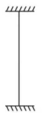
Both ends are restrained against rotation and translation/lateral movement or held in position and direction.
K = 0.5
Leff = L/2
IS Code recommendation , K = 0.65
One End Fixed One End Pinned
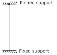
Held in position at both ends but held in direction at one end only or Restricted against translation at both ends, rotation is allowed in one end only.
K= 12=0.707
Leff= L2
IS Code recommendation , K = 0.8
Both Ends Pinned
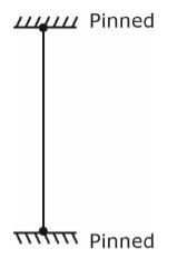
Held in position at both ends or restrained against lateral movement at both ends.
K = 1
Leff = L
IS Code recommendation , K = 1
One End Fixed and Other End Free
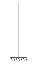
Held in position and direction at one end only or Restricted against rotation and translation at one end only.
K = 2
Leff = 2L
Slenderness Ratio
The slenderness ratio is the effective length ratio to the least lateral dimension.
λ = Leff/b
Where,
- λ = Slenderness ratio
- Leff = Effective Length
- B = Least Lateral Dimension
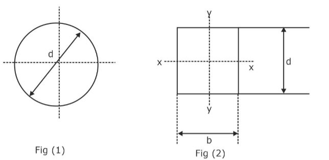
- Least lateral dimension in the case of figure 1 is ‘d’.
- Least lateral dimension in the case of figure 2 is a min of (b,d).
Limits of Slenderness Ratio
Both ends restrained
L/b <60= L <60b
One end restrained
L < 100b2/d
Classification of Columns based on Slenderness Ratio
Short Column
It is that column in which the ratio of effective length to least lateral dimension ratio is less than 12.
3 < λ ≤12
Shorts columns always fail because of direct compression.
Long / Slender Columns
It is that column in which the ratio of the effective length to least lateral dimension is more than 12.
λ >12
Elastic Instability
Columns might fail by crushing or buckling.
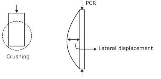
Where Pcr – Buckling Load / Crippling
Columns and Struts which fail by buckling are analyzed by Euler’s theory.
Assumptions for Euler’s Equation for Elastic Instability
Material is homogenous, isotropic, and elastic. The cross-section area of the column remains uniform from top to bottom. The line of thrust coincides exactly with the axis of the column. The column is initially straight, loading must be axial and self-weight is negligible.
Euler’s Theory of Buckling
Moment at x-x axis
M = Py
As per the double integration method,
EId2y/dx2=-Py
d2y/dx2+ (P/EI)y=0
For second-order differential equation solutions are:
y= c1 cos√(P/EI) x+ c2 sin√(P/EI) x
Boundary conditions at x=0, y=0. Therefore, c1 = 0
At x=L, y=0
√P/EI L=nπ
P= π2EI/L2 (Both sides pinned joint)
Generalized Euler’s Formula
Pcr= π2EI/KL2
Where
KL = Effective Length
K = Effective Length Factor
L = Actual Length
Rankine’s Theory For Columns
Euler’s formula doesn’t provide accurate results for columns and struts of medium length. Rankine’s theory can be used for both long and short columns. Rankine’s theory assumes combined modes of failure due to buckling and crushing. Rankine gave an empirical formula :
1/P= 1/Pc+ 1/Pe
Where
P = Combined Load
Pc = Crushing Load
Pe = Euler’s Buckling Load
P= fc A/(1+ αλ2)
Where α= fc/π2E Rankine Constant
λ = Slenderness Ratio
fc = Crushing Strength
For Long Column,
The value of λ >> λc
Pe will be small.
1Pe> 1Pc
Therefore, P = Pe
Long Columns fail under buckling.
For Short Column,
The value of λ << λc
Pe will be small.
1Pe< 1Pc
Therefore, P = Pc
Short Columns fail under crushing.
Columns and Struts Solved Problems
Problem 1: A rectangular column of dimension 40mm x 60mm and length of 3m has the end conditions as given:
“Restrained against rotation and translation at both ends”. Find the buckling load if E = 2 x 10⁵ N/mm2.
Solution- Restrained against rotation and translation at both ends refers to the support system where both ends are fixed.
The effective length factor K = 0.5.
Leff = 0.5 x L
= 0.5 x 3000 = 1500mm
Pcr= π2EImin/leff2
= 280.75kN
Problem 2: There are two columns, A and B, and both the columns have the same E, L, and I. The effective length factor is 2 and 0.707 for columns A and B respectively. Determine the ratio of the buckling load of column B to column A.
Solution- P= π2EI/KL2
PA= π2EI/4L2
PB= π2EI/0.5L2
PB/PA=8
Problem 3: Given the Euler’s Buckling load for a column as 100kN and crushing load as 120kN. Find the Rankine Load (in kN).
Solution – Given, Pcr = 1000kN, Pc = 1200kN
1/P= 1/Pc+ 1/Pcr
P= PcPcr/(Pc+ Pcr)= 1200 ×1000/(1200+1000) = 545kN
Problem 4: A column of 1.5m long (diameter 50mm) is free at one end and fixed at another end. Crushing stress = 600 MPa. Find safe failure load if the factor of safety = 3. α = 1/1600.
Solution – K = 2
Leff = KL = 2 x 1.5 = 3000mm
fc = 600MPa, α = 1/1600
Safe Failure Load= Rankine Load (P)/ FOS
Rankine’s Load=P= fc A/(1+ αλ2)
λ= leff/ Rmin
Rmin= √Imin/A
D/4=0.5mm
λ= 3000/12.5=240
P=31.8kN
Safe Load= 31.8/3=10.61kN


