- Home/
- GATE ELECTRONICS/
- GATE EC/
- Article
BJT Amplifier
By BYJU'S Exam Prep
Updated on: September 25th, 2023

BJT Amplifiers play a vital role in a lot of applications. Bipolar Junction Transistors (BJT) can be operated mainly in three regions. Those are Saturation, Active and Cut-off regions. To work BJT as an amplifier it should operate in the active or linear regions. Based on the requirement, we will use the respective BJT amplifiers.
BJT is the basic transistor among all the transistors. Hence, it is easy to understand the working of JFET amplifiers and MOSFET amplifiers after studying and understanding the working of BJT Amplifiers. In this article will discuss the BJT Amplifier along with its types and operation respectively.
Table of content
What is BJT Amplifier?
The electronic circuit which performs amplification is known as an Amplifier. The transistor is the main component in Amplifiers. Bipolar Junction Transistor (BJT) is the basic transistor among all transistors. So, if we use BJT in the amplifier circuits, those are known as BJT amplifiers.
BJT Amplifier Circuit
The following figure shows a circuit diagram of a typical BJT Amplifier.
As the name implies, amplifiers will amplify the level of the input signal and produce the output. So, we can classify the Amplifiers into three types according to the quantity amplified at the output. Those are voltage amplifiers, current amplifiers, and power amplifiers.
Formulas for GATE Electronics & Communication Engineering – Signals Systems
Types of BJT Amplifiers
We can classify the BJT amplifiers in various ways based on different parameters. One of those parameters is the BJT configuration. Since we have three BJT amplifier configurations, we will get three types of BJT amplifiers. Now, let us discuss the following three types of amplifiers one by one.
- Common Base (CB) Amplifier
- Common Emitter (CE) Amplifier
- Common Collector (CC) Amplifier
Formulas for GATE Electronics & Communication Engineering – Communication Systems
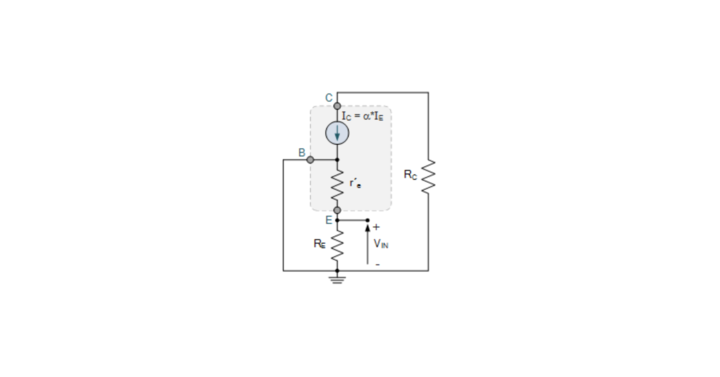
Common Base Amplifier
As the name implies, Base is common to both input and output in the Common Base (CB) configuration. Here, we will consider the Emitter and Collector terminals of the BJT as the input and output terminals. The circuit diagram of the BJT Amplifier, which is configured in Common Base (CB) is shown below.
In this BJT Amplifier, the AC voltage waveform, which is applied at the emitter terminal, will be amplified and produced at the collector terminal. This circuit has no phase shift between the input and output waveforms. The characteristics of a CB amplifier are mentioned below.
- Low input resistance
- High output resistance
- High voltage gain
- The current gain is approximately equal to one
Common Emitter Amplifier
As the name implies, an Emitter is common to both input and output in the Common Emitter (CE) configuration. Here, we will consider the Base and Collector terminals of the BJT as the input and output terminals. The circuit diagram of the BJT Amplifier, which is configured in Common Emitter (CE) is shown below.
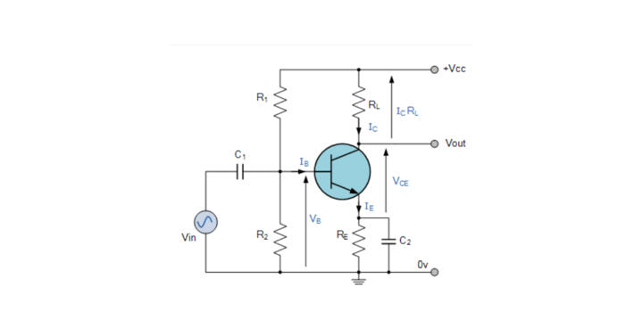
In this BJT Amplifier, the AC voltage waveform applied at the base terminal will be amplified and produced at the collector terminal. But there is an 1800 phase difference between the input and output waveforms. The characteristics of the CE amplifier are mentioned below.
- Medium input resistance
- Medium output resistance
- Medium voltage gain.
- Medium current gain.
Common Collector Amplifier
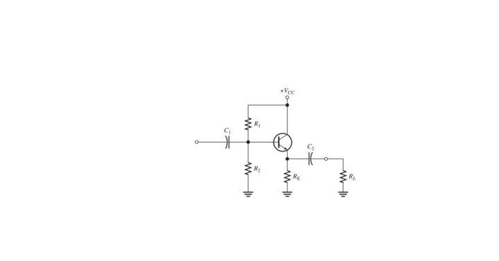
As the name implies, Collector is common to input and output in the Common Collector configuration. Here, we will consider the Base and Emitter terminals of the BJT as the input and output terminals. The BJT Amplifier’s circuit diagram, configured in Common Collector (CC), is shown below.
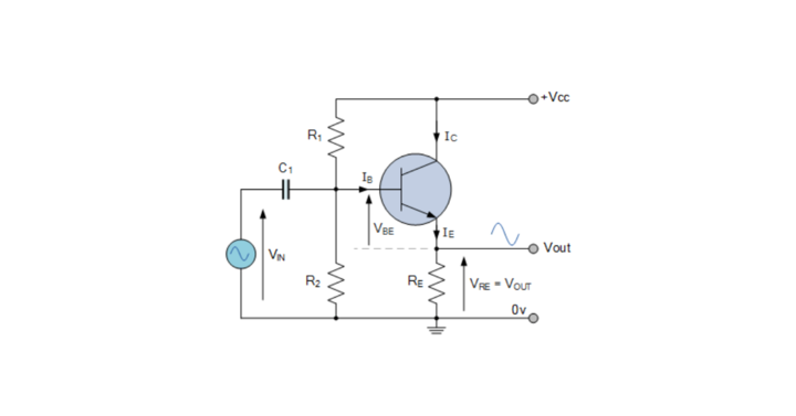
The BJT amplifier configuration with the lowest output resistance is the Common Collector configuration. In this BJT Amplifier, the AC voltage waveform, which is applied at the base terminal, will be produced at the emitter terminal with unity voltage gain. This circuit has no phase shift between the input and output waveforms. The characteristics of the CC amplifier are mentioned below.
- High input resistance
- Low output resistance
- Voltage gain is approximately equal to one.
- High current gain.
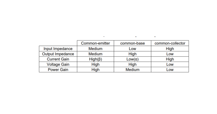
Comparison Between Types of BJT Amplifiers
Here, we have provided a comparison between various Types of BJT Amplifiers based on the I/O impedance and various gains in the circuit in the figure provided below: